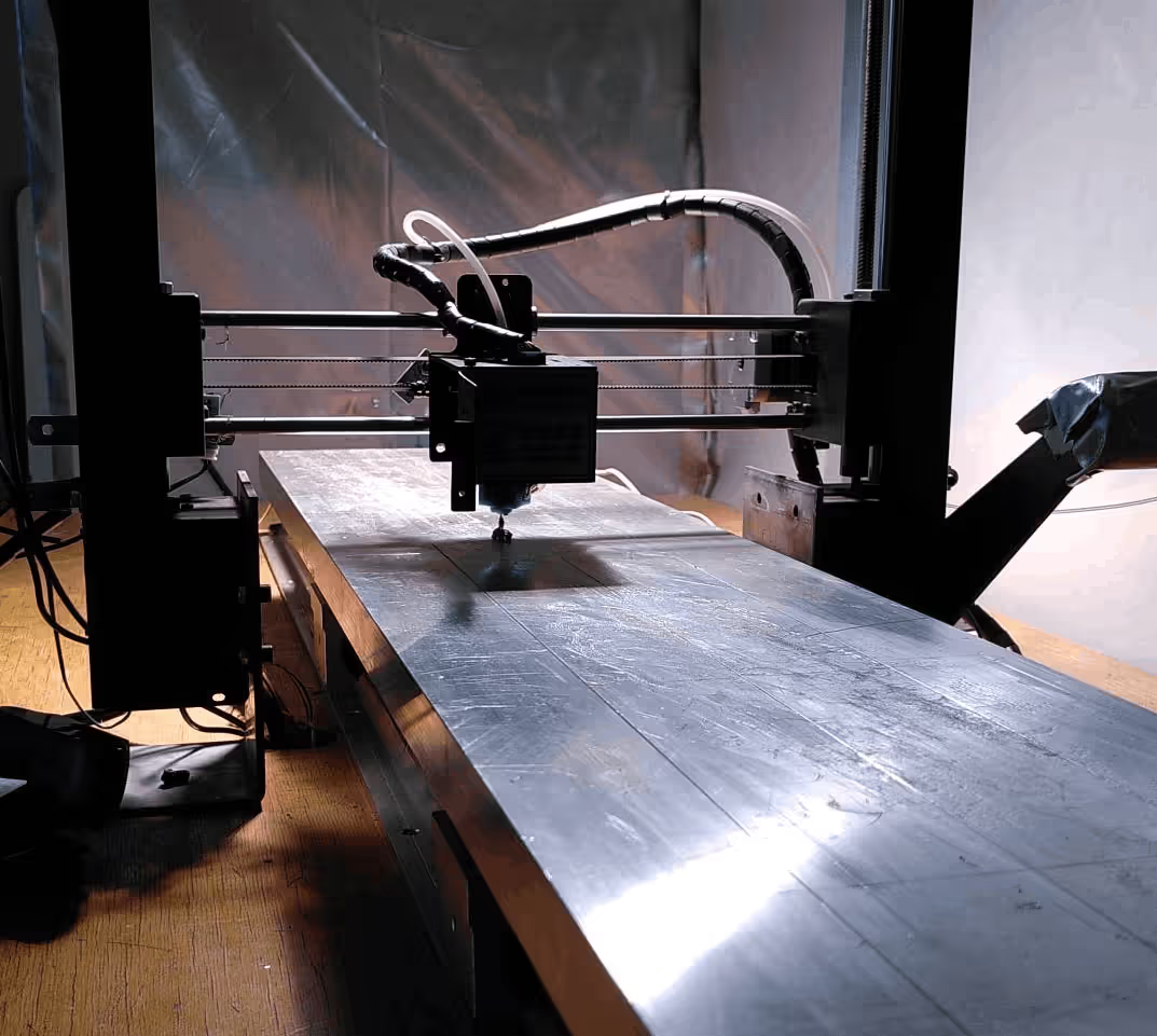
XL Long bed 3D-printer conversion
EXTRUSION
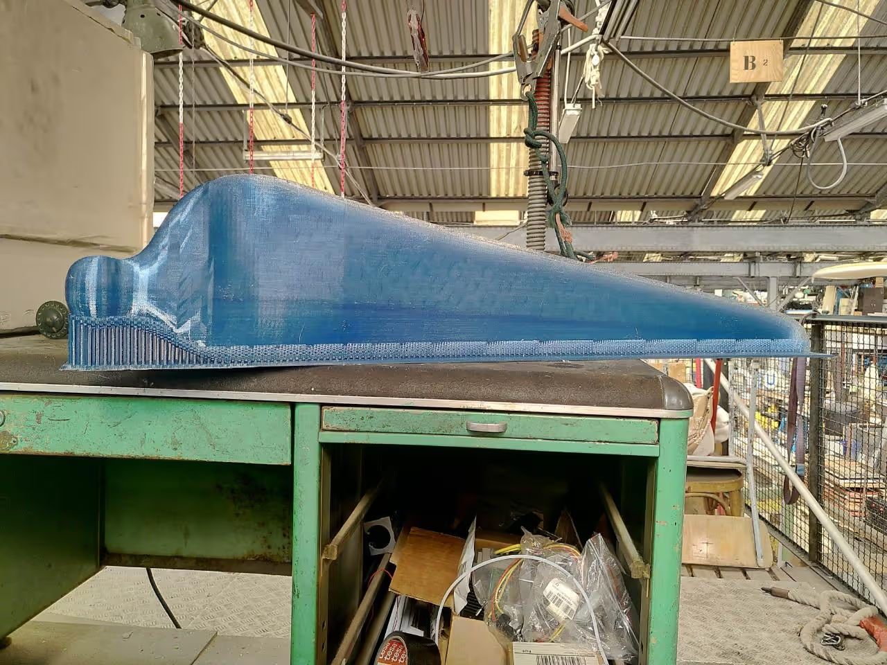
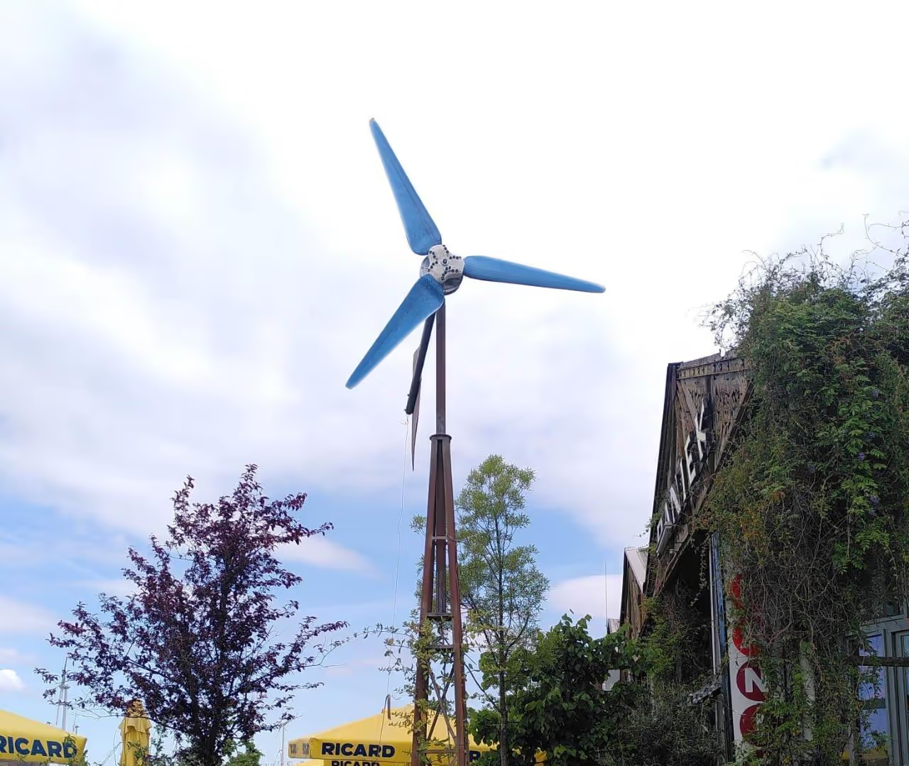
This guide demonstrates fitting a longer bed on a flashable 3D printer. We used such a bed to print wind turbine blades.
Basics:
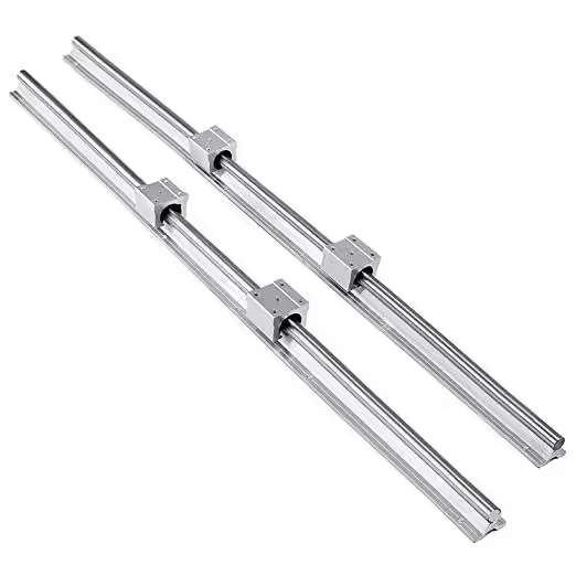
Y-Axis Movement System:
Heated Bed:
Tools:
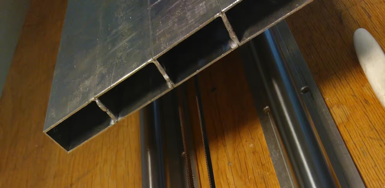
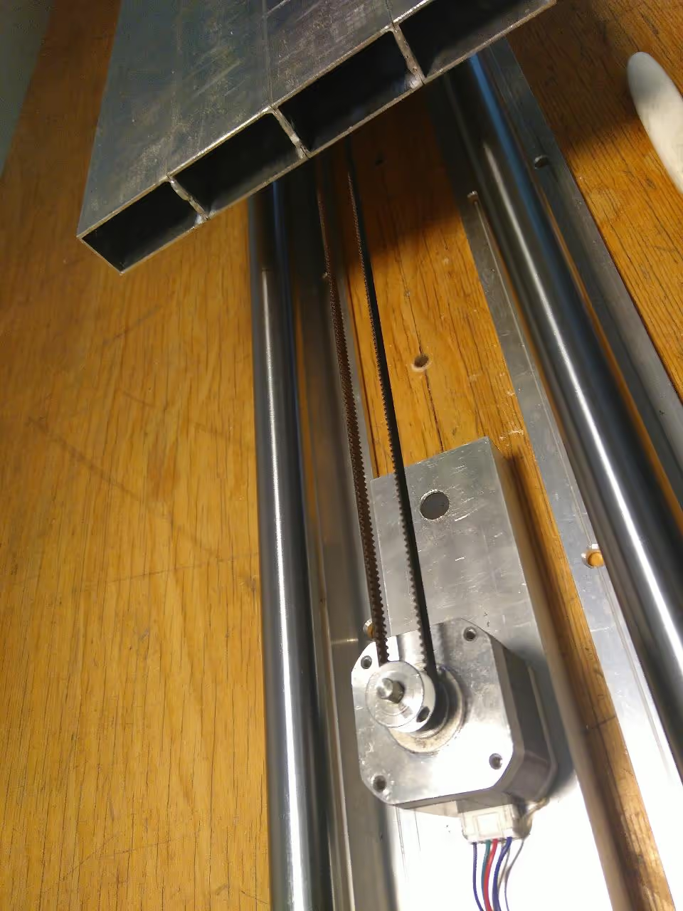
Weld the aluminum profiles to create a platform measuring 3 feet 3 inches by 8 inches (1m by 20cm), ensuring connections are at the ends to prevent distortion.
Drill holes for the bearing holders, spaced 3 feet 3 inches (1m) apart.
Install the bearings approximately 2 inches (5cm) from the bed.
Slide the fiberglass sleeve over the NiCr heating wire and thread it through the aluminum bed's hollow spaces.
Optionally, place fiberglass cloth at the end of each aluminum profile to retain air.
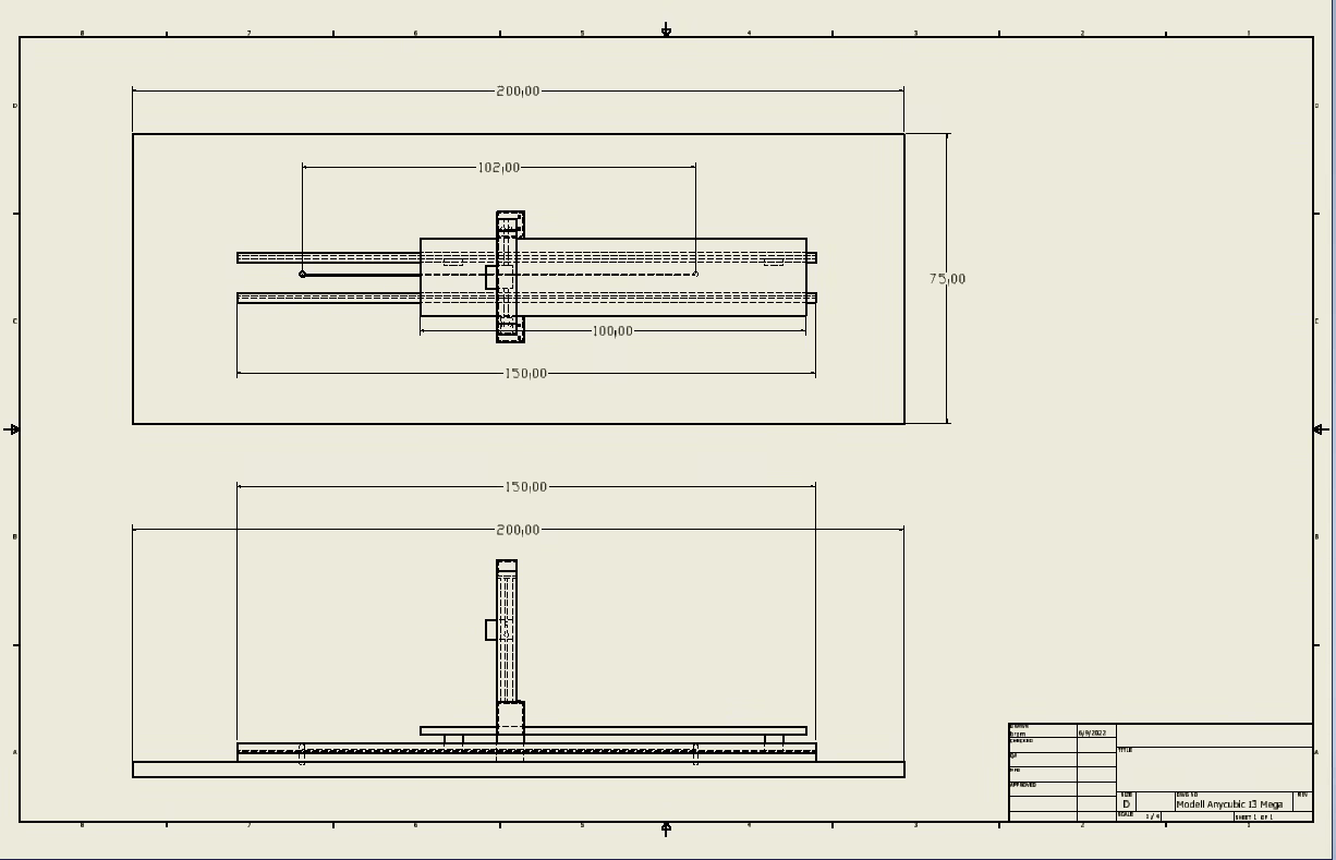
Ensure the table is stable and immobile to maintain print quality. Clean the rails and apply PTFE oil, as they may gather dust during installation. Review the technical drawing for assembly details before proceeding.
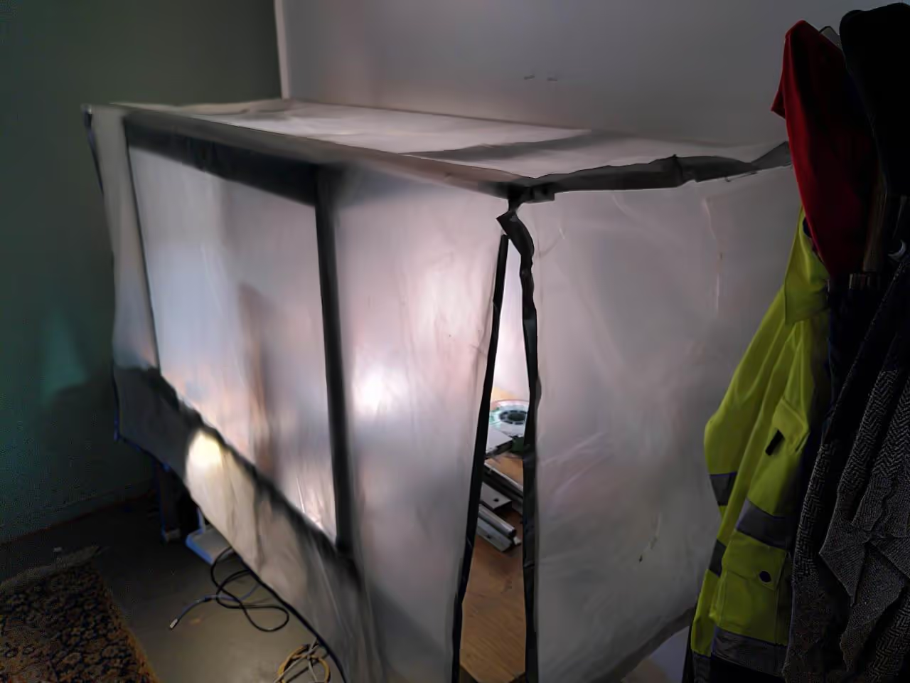
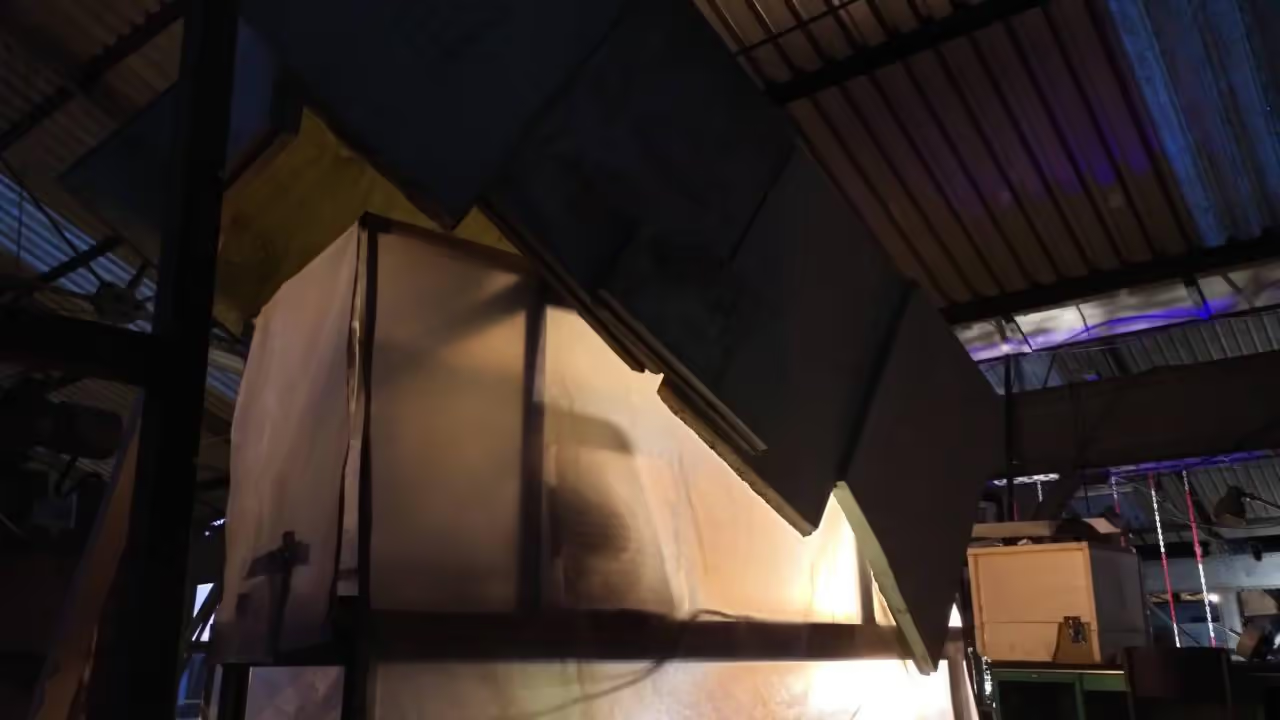
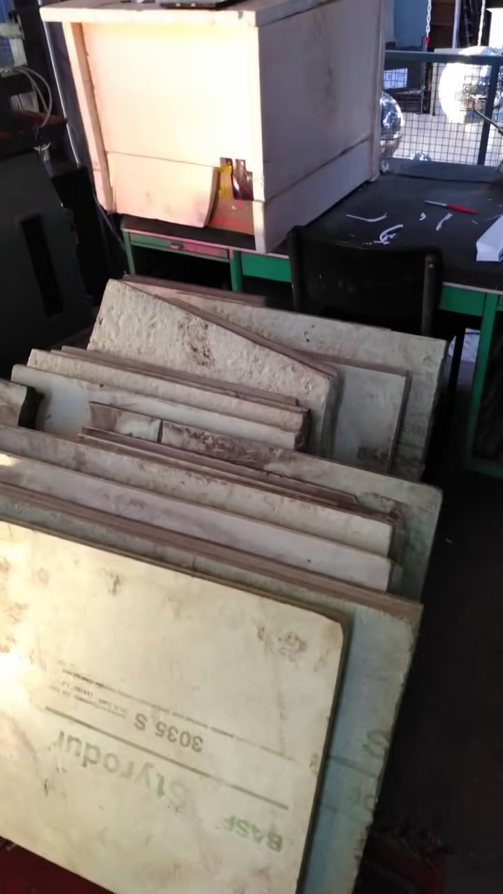
Create a cover for the print area using materials like plastic foil to retain heat, depending on the room temperature. Cardboard or leftover Styropur (a BASF product) can also be effective as sturdy options that do not require additional framing.
An adapted version for the Anycubic I3 Mega S is available here. Later versions had issues with the manual bed leveling system, which is crucial for a properly aligned bed.
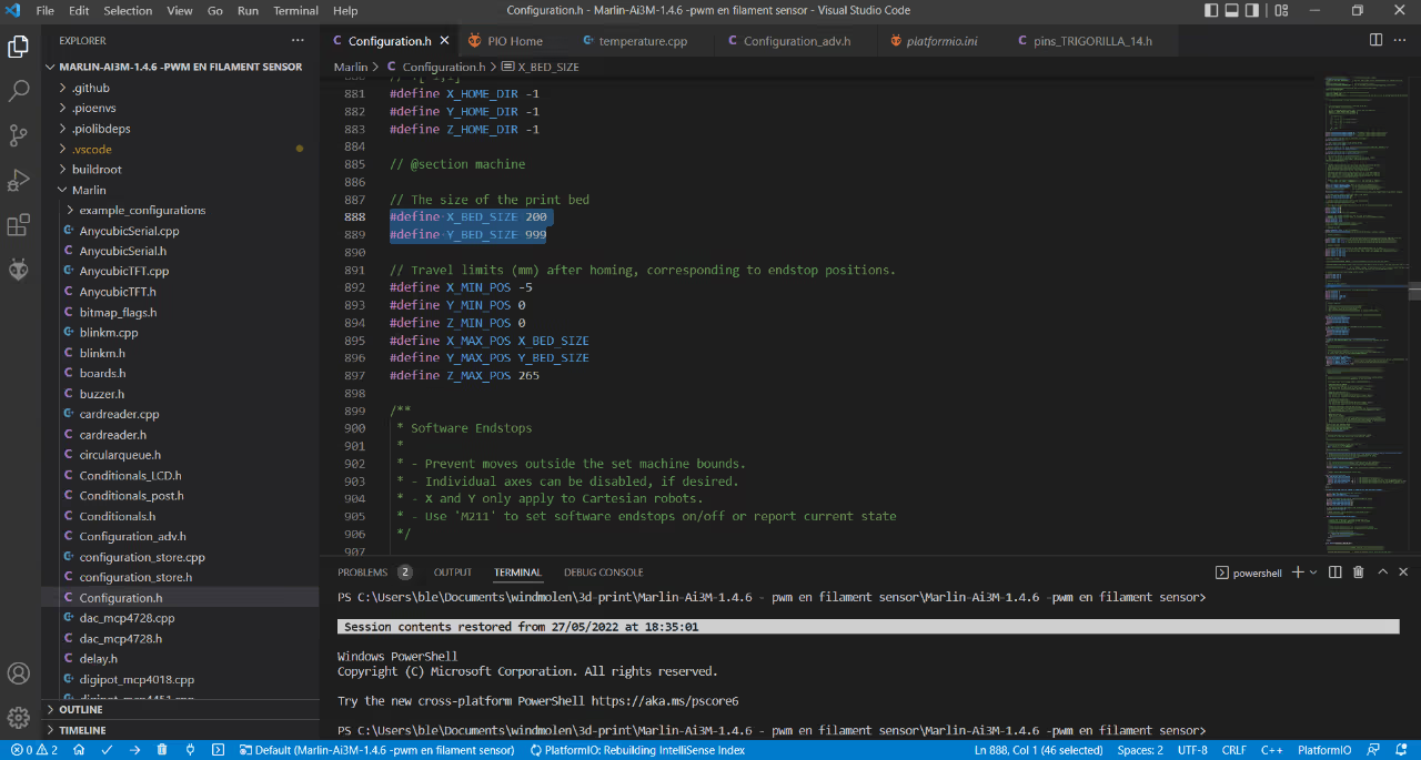
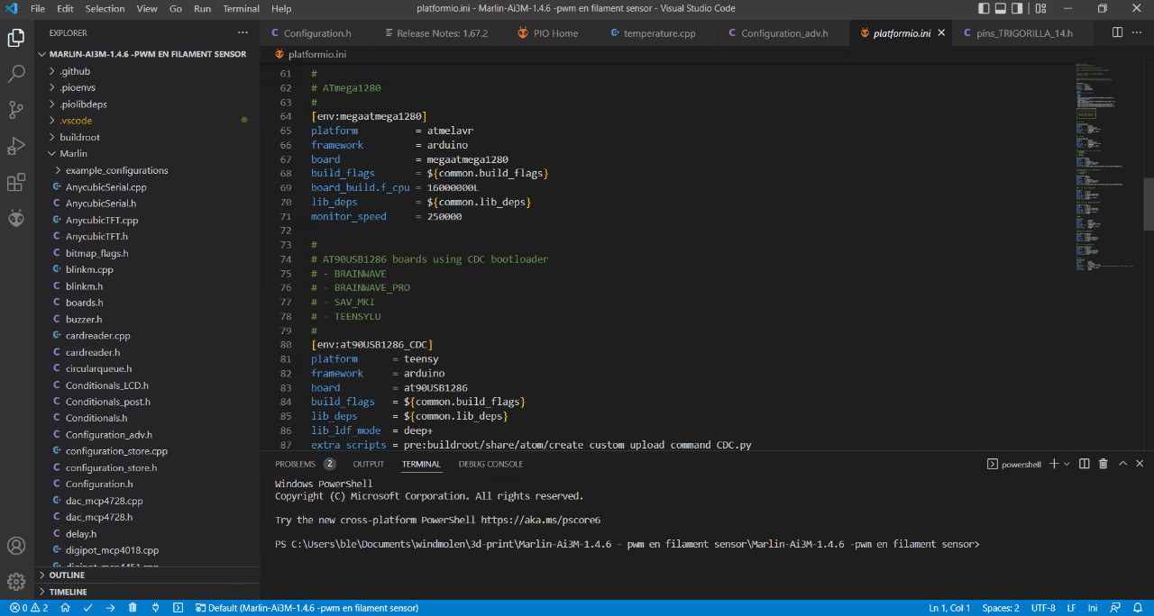
To proceed, install VSCode and open the code. Modify the following settings in configuration.h to accommodate the printer's larger bed and increased build volume:
Connect your printer's mainboard via USB. VScode will automatically detect the correct serial port. Click the small arrow in the bottom left corner to start uploading.
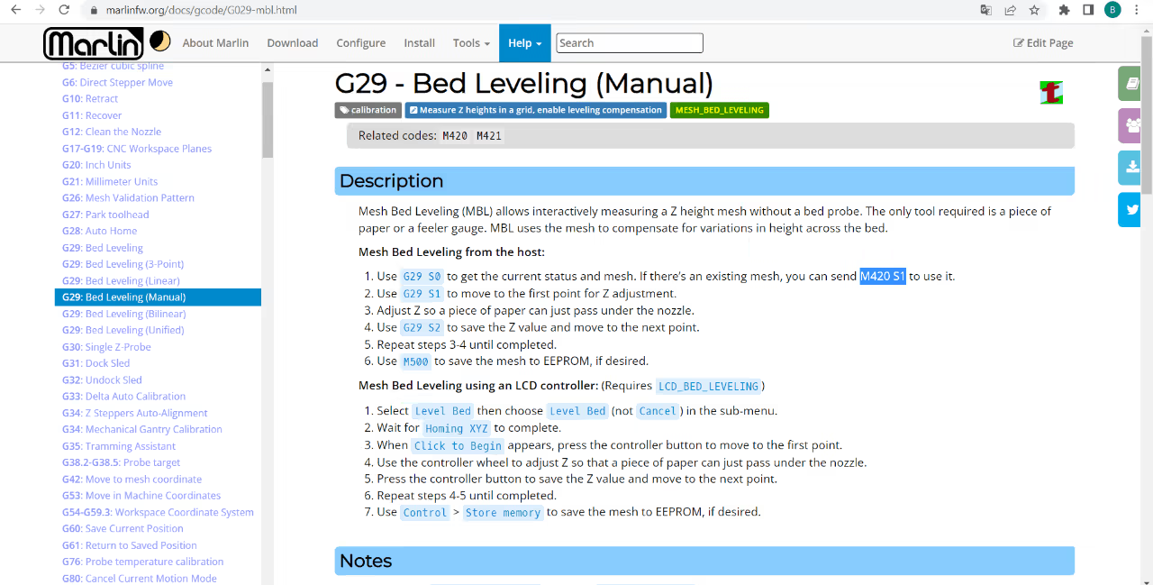
Instead of manually adjusting the four knobs on the print bed, execute the G29 S1 command followed by G29 S2. The printer will calculate a 5x5 grid (can be modified in firmware) across the print bed, allowing you to adjust the nozzle height on the z-axis at each position.
For detailed information on the G29 command in Marlin firmware, visit Marlin Documentation.
Once adjustments for all 25 points are complete, the printer will beep and reset the print head to its 0,0 position. Ensure you save the grid using the M500 command. Before each print, use M420 S1 to enable mesh-bed-leveling and load the adjusted z-coordinates. Consider adding this command to your slicer's custom g-code section to automate the process for every print.
Printing large objects can present challenges, such as adhesion issues. Larger prints are prone to warping and detaching from the printing bed. We achieved good adhesion results using rPET, PETG, and PLA combined with Formfutur's Magigoo adhesive. PET(G) adheres particularly well, and we apply a first layer of PET(G) when printing with ABS.
This extended bed modification enables the printing of wind turbine blades, allowing you to construct your own wind turbines.