Trash Printer Flake Extruding 3D Print Head
PP
OTHER MACHINE
HDPE
EXTRUSION
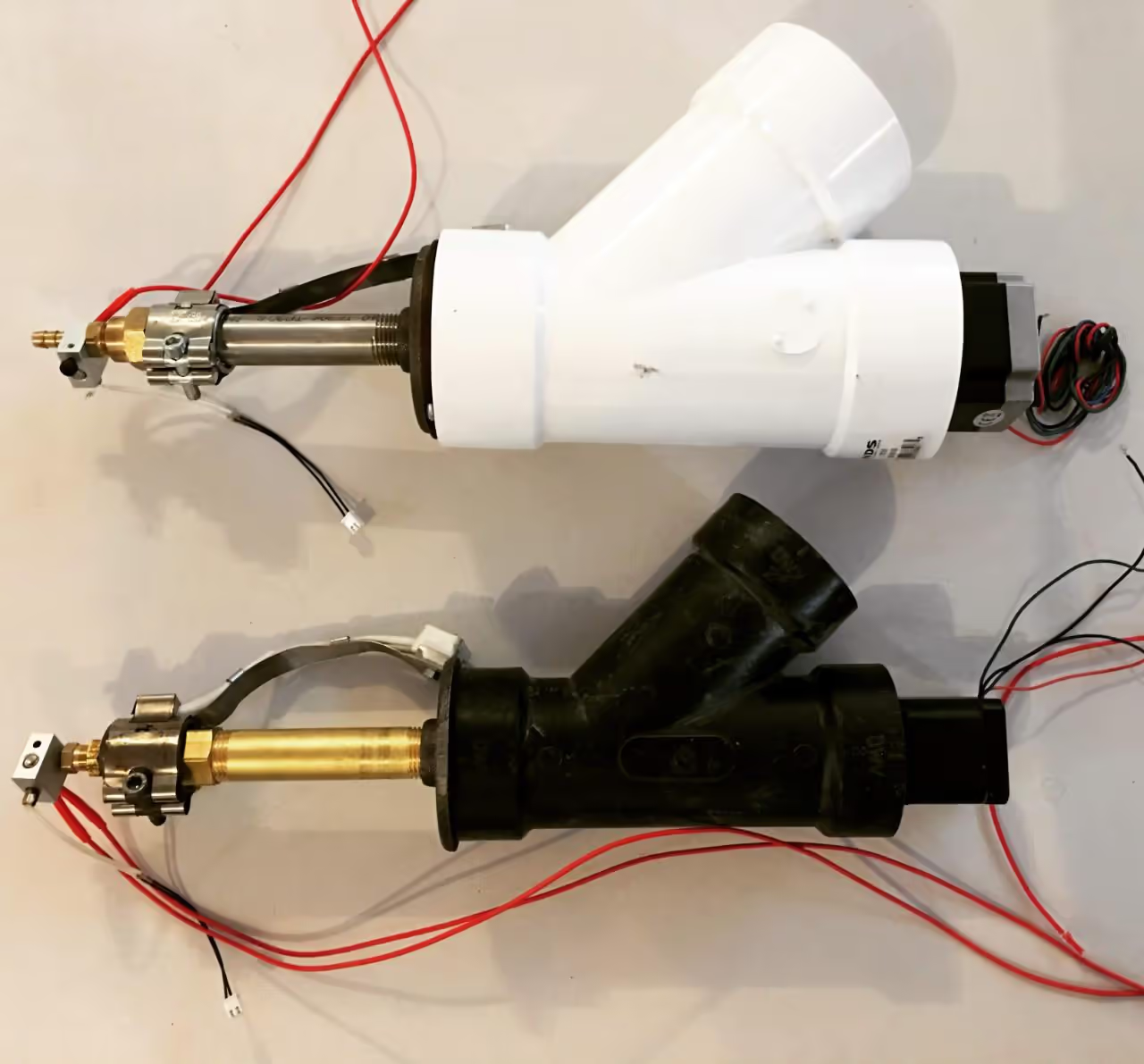
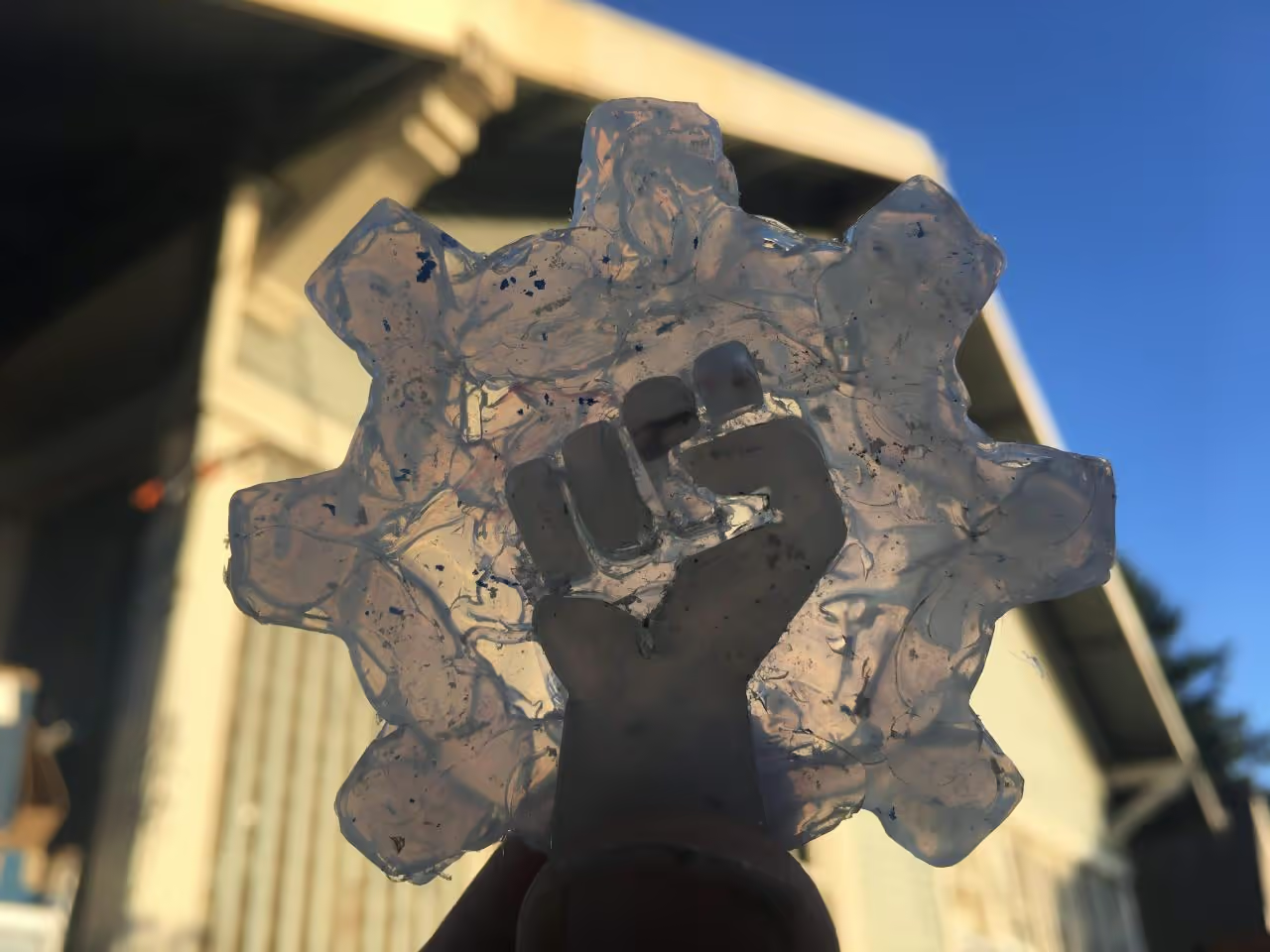
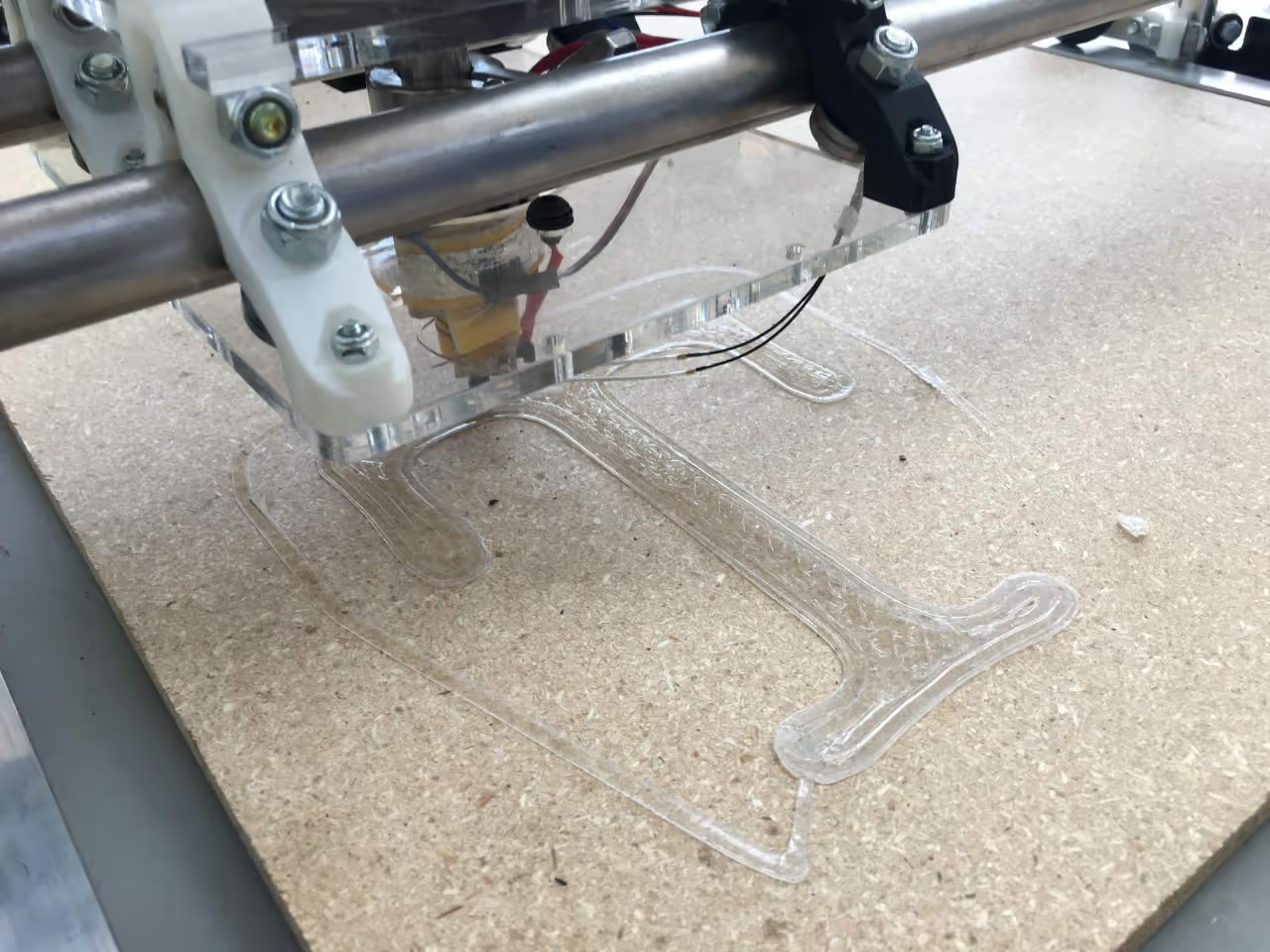
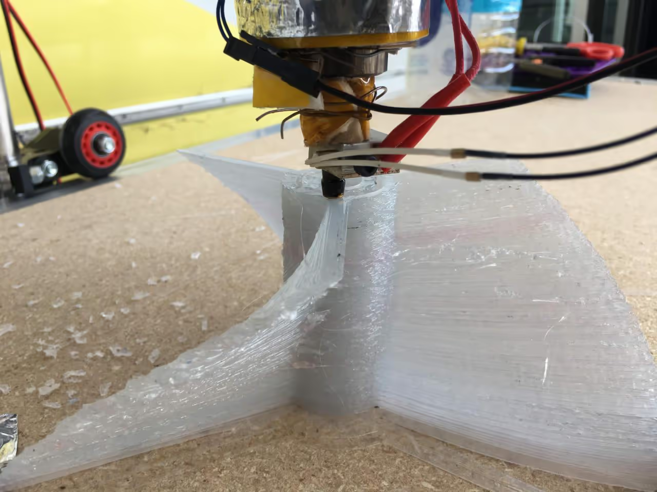
This is a modified extruder design, optimized for large-format 3D printing of Polypropylene, using shredded plastic flakes instead of filament.
First, watch the build video to understand the assembly process. The extruder head for the trash printer is a modified version of the filtered extruder, featuring a vertical axis and a NEMA23 stepper motor for easy integration with standard 3D printing software.
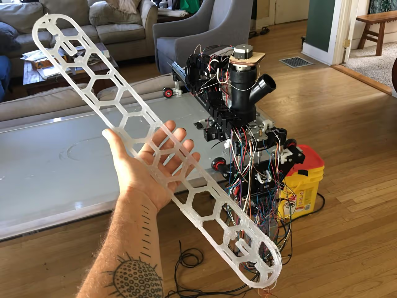
This tutorial explains how to build the print head. To start printing, attach it to a CNC gantry capable of moving and running g-code. The example uses the MPCNC LowRider2 gantry by V1Engineering, which, while not technically open-source, is notable for its design utilizing 3D printable parts and readily available hardware.
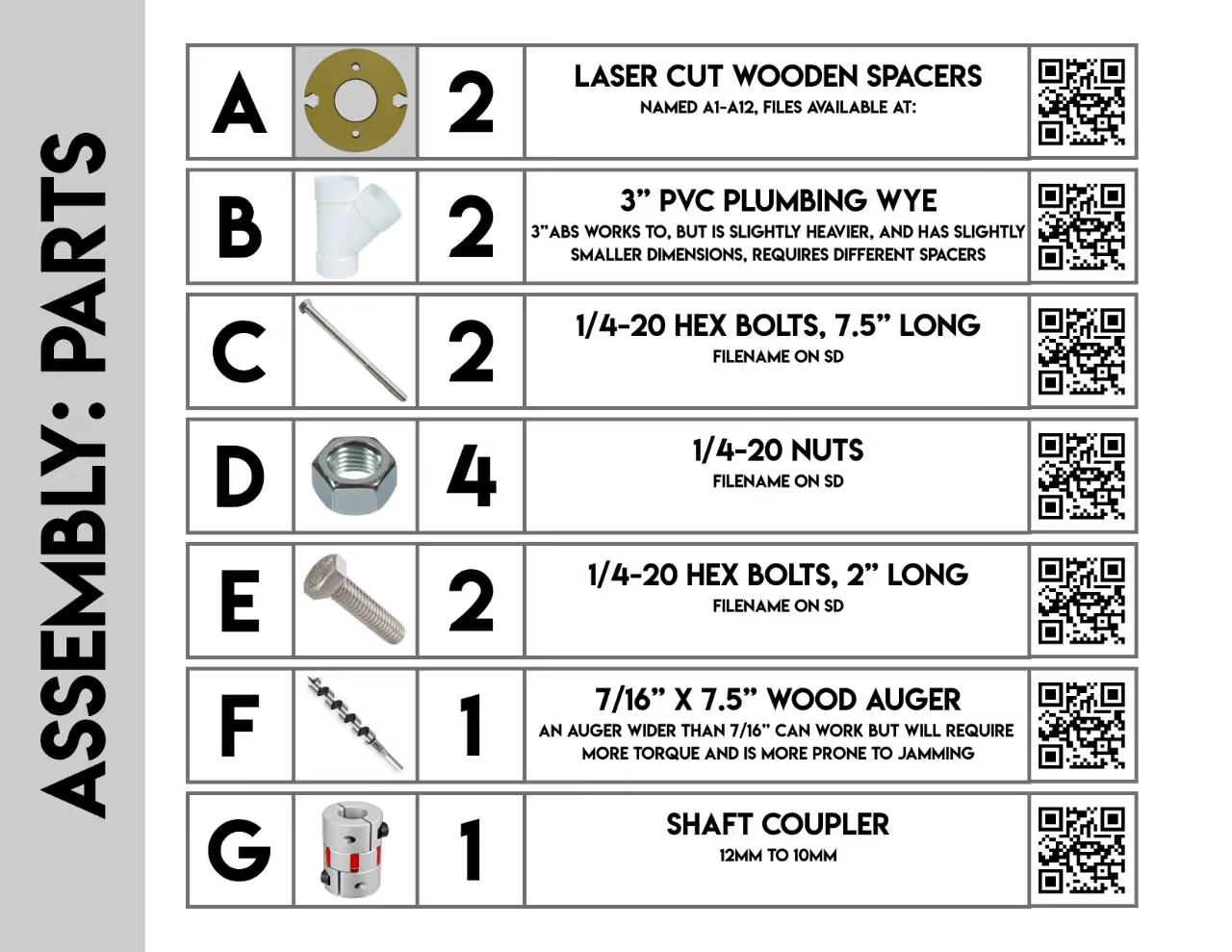
Parts Required for Trash Printer Extruder Assembly:
The components necessary for this project can be sourced from local hardware stores or online retailers like Amazon. The estimated total cost ranges from $150 to $200, largely due to the motor expense. Other components are relatively inexpensive.
The design uses a 3-inch (7.62 cm) PVC plumbing wye fitting as a hopper. This fitting is commonly found in the United States; however, dimensions may vary internationally, necessitating modifications to custom parts.
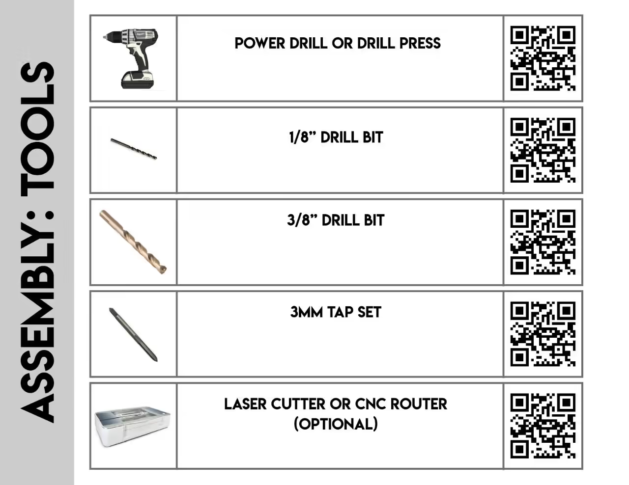
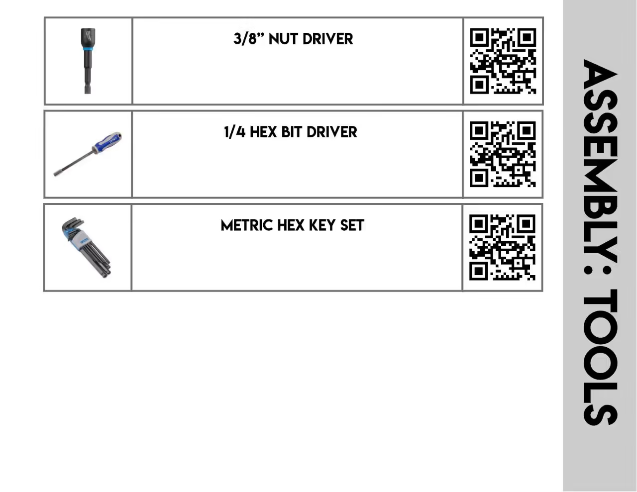
Essential tools include basic items and a laser cutter or CNC router for cutting wooden spacers to assemble the extruder. If unavailable, you can use the provided files as guides to cut and drill by hand. Various materials are suitable for spacers, though wood is preferred for its durability and resistance to heat-related softening.
The bottom flange won't heat enough to burn wood but can melt plastic; hence, wooden bottom spacers are advised. Top spacers and adapters can be 3D printed from plastic if desired.
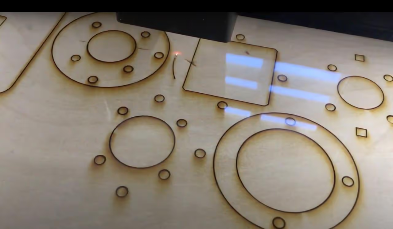
In the attached zip folder, you will find a set of .svg files for cutting the necessary spacers. These can be cut using a laser cutter, CNC router, or manually drilled if necessary. My equipment used was a Glowforge Basic laser cutter.
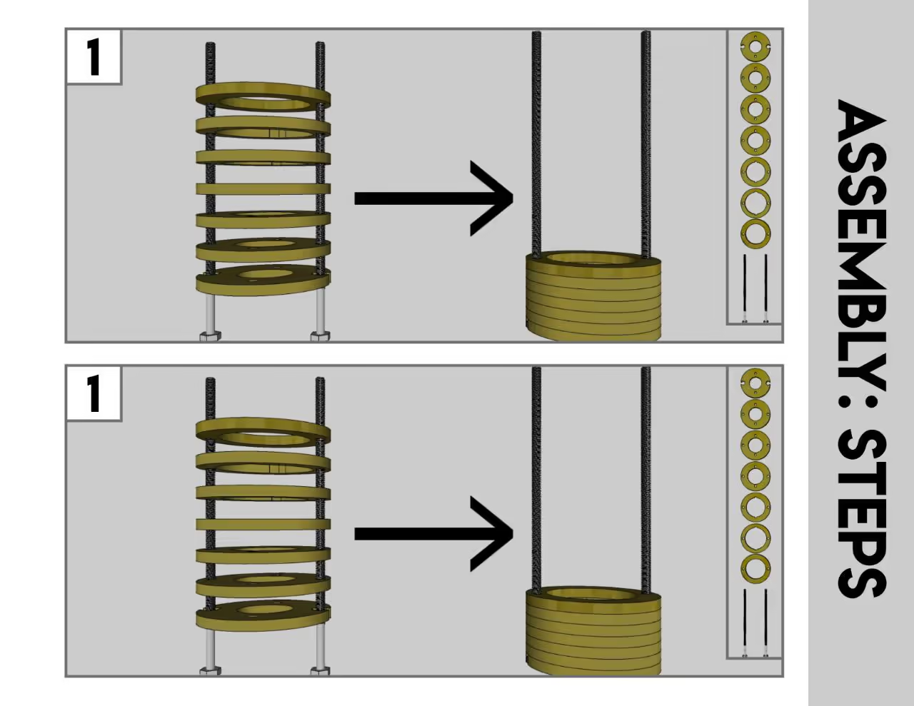
Place all bottom spacers, beginning with B1, onto the two long threaded bolts. Arrange them in order from the smallest to largest hole; there should be seven. If your material is thinner than 0.25 inches (6.35 mm), additional spacers may be required.
Secure the nuts onto the spacers, then insert the smaller bolts from the opposite direction. Fit the pipe flange over the shorter bolts, covering the recessed heads of the longer bolts, and secure with nuts.
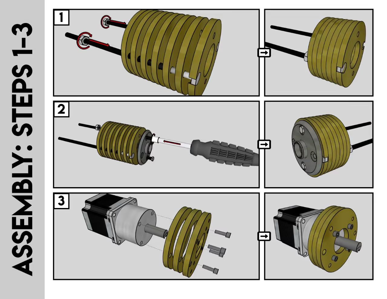
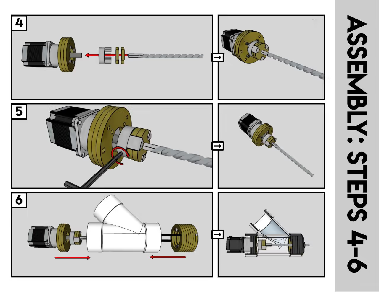
Place two top spacers (T2) behind the T1 motor bracket. Attach the NEMA 23 Stepper motor to the motor bracket spacer (T1) using M4 bolts.
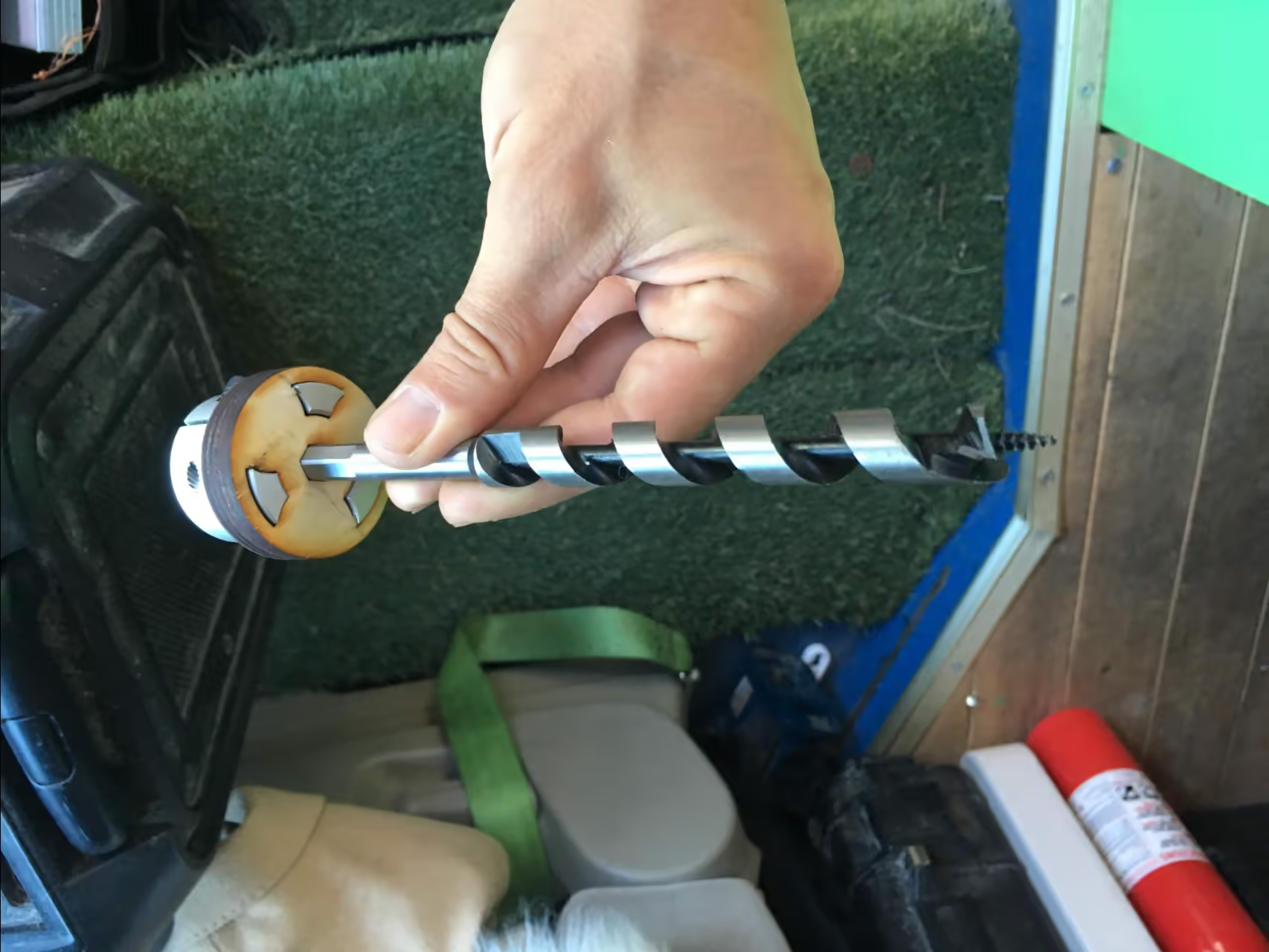
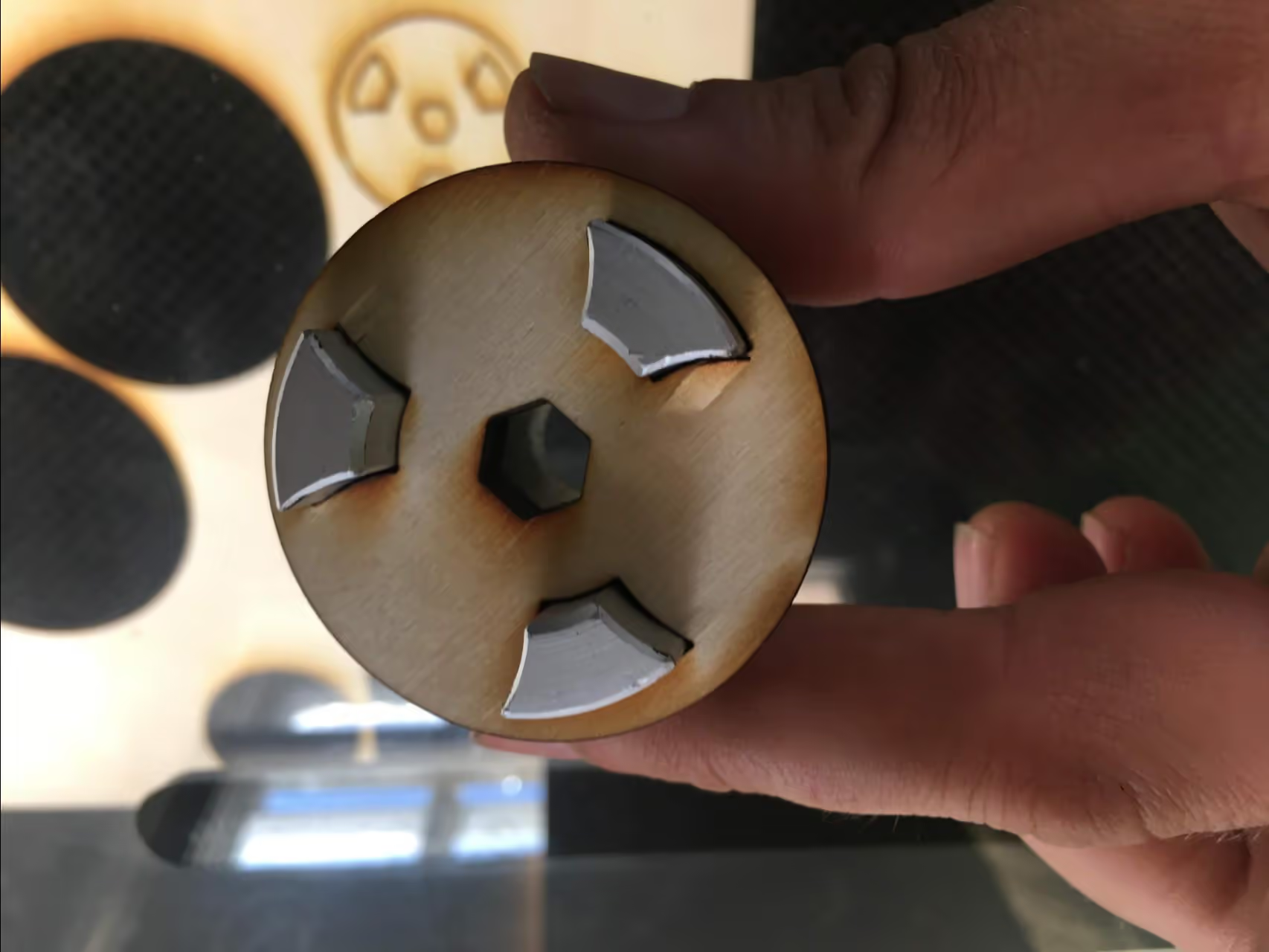
Secure the shaft coupler onto the motor spindle using a hex wrench, then press-fit the shaft coupler adapter into the gear teeth. This accommodates a standard US hex shank for most 7/16" (11 mm) drill bits. The internal hex shape can be adjusted for different auger shanks.
Align and connect the two assemblies by sliding them so that the bolts from the bottom assembly align with the holes in the top assembly and push through.
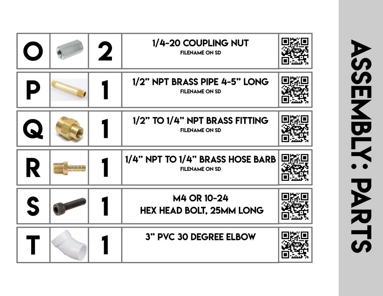
Tighten the 1/4"-20 coupler nuts onto the ends of the threaded bolts. If the fit is tight, use a ratchet tool. Additional spacers (B7 or T2) may be added to adjust the auger's extension into the extrusion tube; generally, 1-2 inches (2.5-5 cm) is sufficient. Ensure the auger does not extend too far into the melt zone to avoid locking when the material cools.
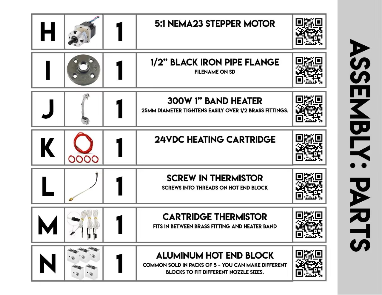
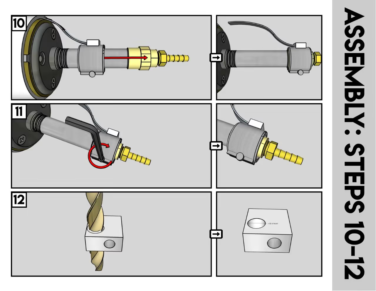
Proceed to assemble the extrusion barrel and slide the heater band onto the brass adapter.
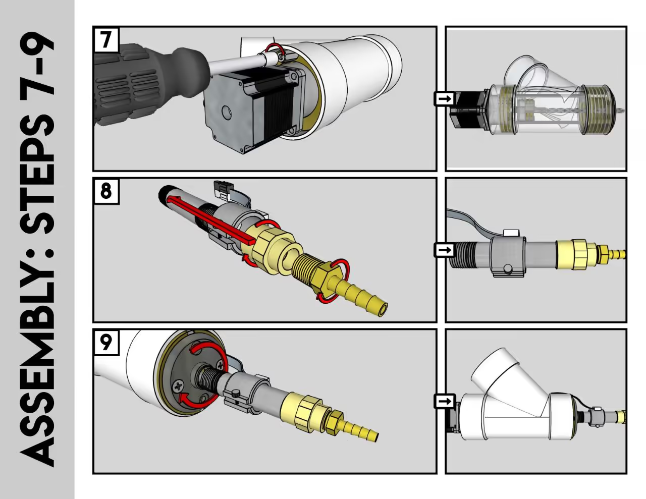
Attach the pipe to the pipe flange, ensuring it is hand-tightened without thread tape until it no longer turns.
Position the heater band securely. Insert the thermistor probe between the band and the pipe, ensuring it remains firmly in place.
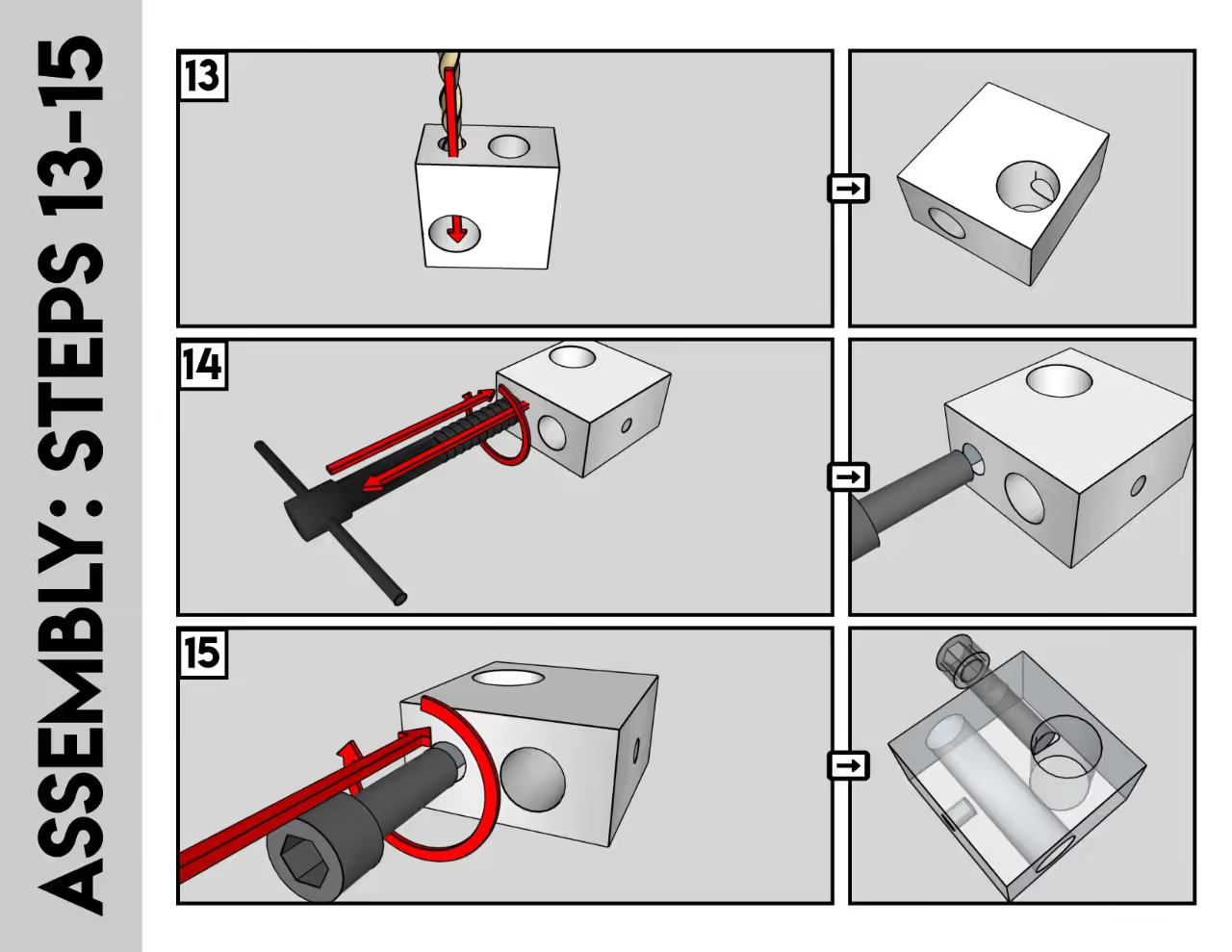
Drill the Aluminum Block: Enlarge the hole in the aluminum hot end block with a drill. Ensure it fits snugly around the barbed nozzle.
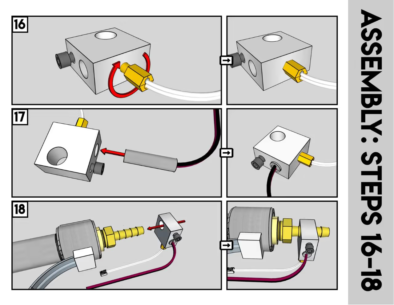
Secure the Hot End: Position the hot end on its side. Drill and tap a hole for a set screw to secure the hot end against the nozzle.
Install Components: Insert the heater cartridge and screw-in thermistor into the hot end, ensuring a proper fit.
Assemble and Adjust: Slide the modified hot end assembly over the nozzle barb and tighten it in place, approximately 1/2 inch (12-13 mm) above the nozzle's end. Ensure the block is close to the nozzle tip, but not so close as to be covered in plastic during use, which could produce unwanted fumes.
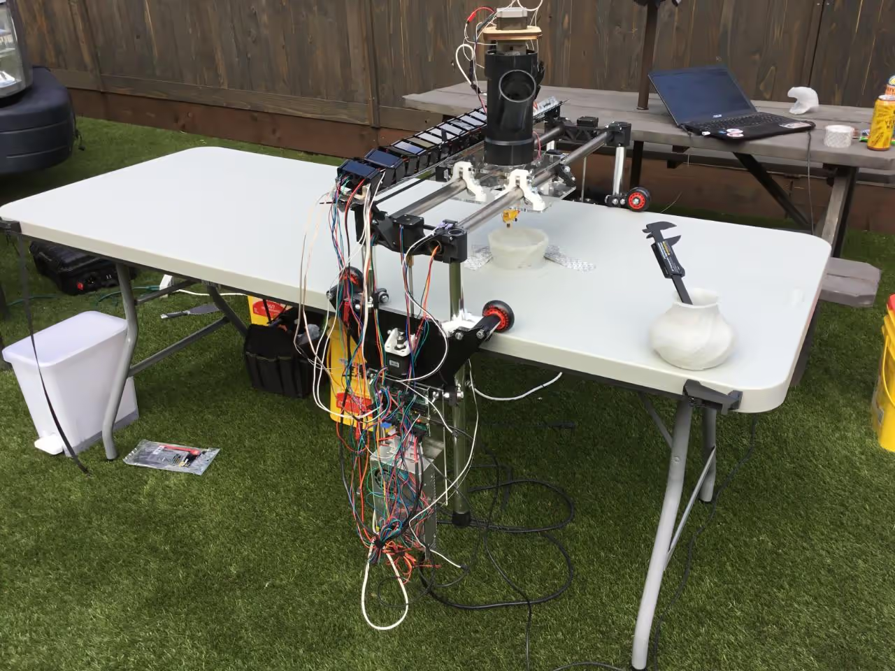
Mount the extruder onto a suitable CNC gantry. This is a technical task; I use an MPCNC Low-Rider2 with a RAMBOv1.4 board running Marlin firmware and Repetier-Host control software.
The NEMA23 operates optimally at 24V. I power the system with 24VDC using a Solid State Relay (SSR) module to control AC mains power for the band heater. The SSR is managed by the heater relay on the control board. When activated at 24V, it powers the SSR, turning on the mains switch to deliver increased power to the extruder.
This design was inspired by [filtered] and is entirely open source. You may use, share, and modify it freely. If you choose to replicate or improve the design, feedback and contributions are appreciated.
For further information on my open-source infrastructure designs and updates on my projects, visit Patreon.com/DisruptivelyUseful.