Create a shut off for the beam mould
UNTAGGED
EXTRUSION
MOULD
This guide explains how to create a shut-off mechanism for a beam mold, ensuring no plastic leakage after detachment from the extrusion machine.
Materials Needed:
Instructions:
Follow these steps for an effective solution.
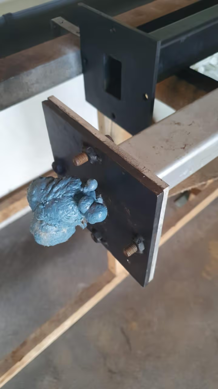
When using the extrusion machine, we aimed to control the plastic outflow once the mold is filled and detached from the nozzle. Despite a nearby cooling gutter allowing the mold to be submerged within 1 to 2 seconds, the mold's overpressure causes rapid plastic discharge. This results in additional waste and requires time and effort to clean. Our solution is as follows:
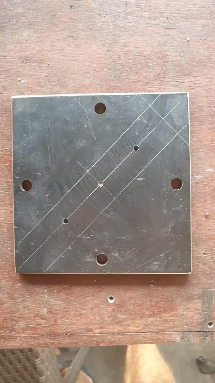
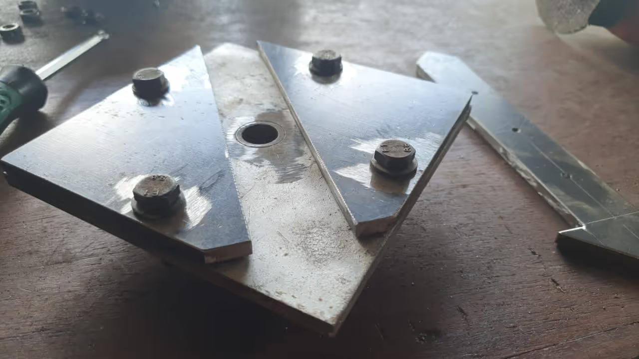
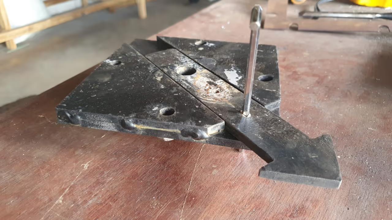
To close the beam mold from the extrusion machine while it remains connected, use an additional steel plate with matching dimensions and hole pattern to the other two plates. Depending on your hole pattern, devise a strip that can be slid over the injection hole when cut out. We used an arrow shape to establish a fixed stopping point.
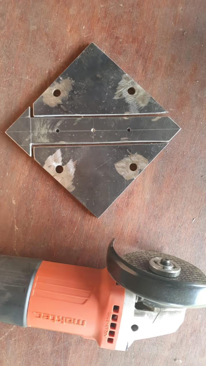
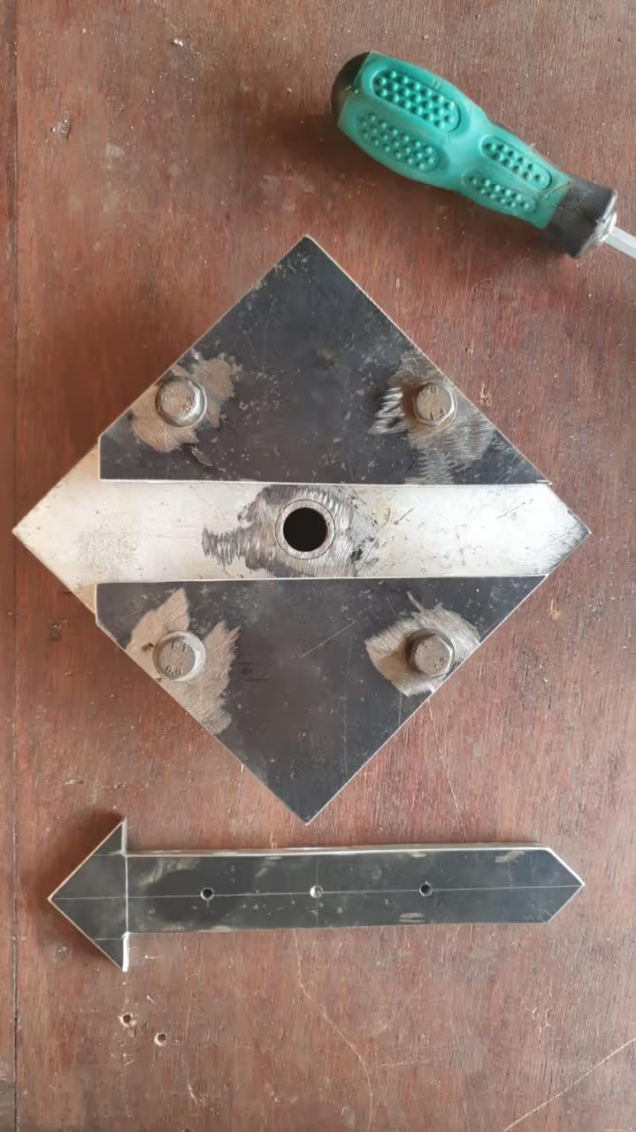
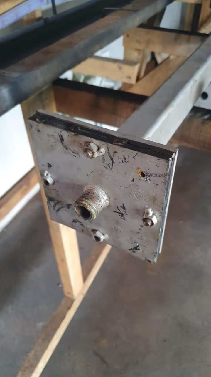
After cutting out the slide strip, attach the two symmetrical parts to the nozzle plate and tack weld them (refer to image 1). Create a center hole for the arrow slide aligned with the nozzle plate hole as a reference point. We found it effective to extend 1.57 inches (4 cm) from the center point to drill two holes: one 0.16 inches (4 mm) near the arrowhead and another 0.79 inches (20 mm) further. In the open position, the 0.79-inch hole aligns with the nozzle hole (refer to image 3). In this alignment, drill the 0.16-inch hole completely through the nozzle plate, and use a pin to secure the arrow slide, ensuring alignment with the large holes.
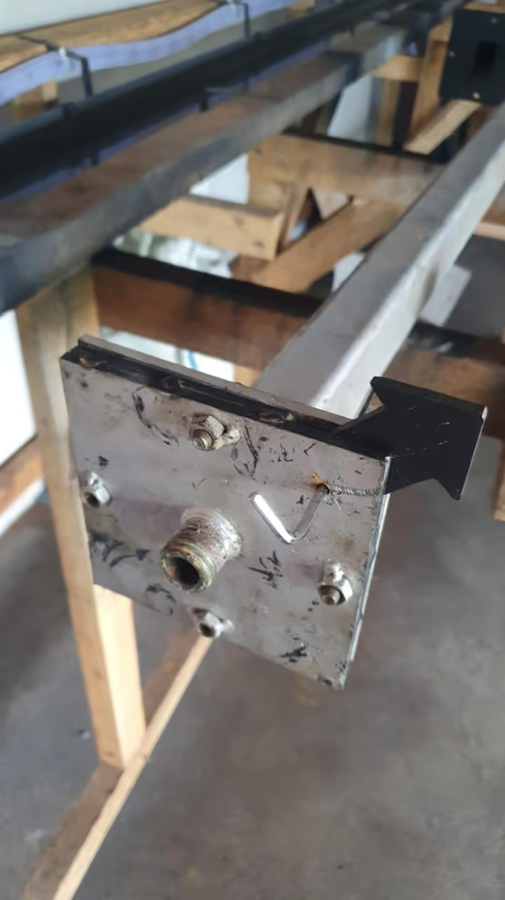
Drill an additional 0.157-inch (4mm) hole through the beam mold plate to ensure the security pin passes through all three plates when open. Begin extrusion by sealing the end of the mold, leaving only a 0.197-inch (5mm) pressure relief hole as a fill indicator. Continue extruding slightly longer to apply pressure to the beam. Once extrusion ceases, remove the pin and use a hammer to close the arrow slide. Unscrew the mold carefully, allowing it to cool appropriately. After cooling, detach the nozzle plate. The beam should slide out easily, or lightly tap the back if needed. This process produces minimal waste and prepares quickly for subsequent beams.
To address the extrusion mold shut-off challenge, the solution involves precise mechanical modifications and specialized tools. Below is a concise breakdown of required components:
These components enable the creation of a reusable, leak-resistant mold system. The process emphasizes precision in drilling (±0.5mm tolerance) and robust welding to withstand extrusion pressures exceeding 50 bar[1][3].