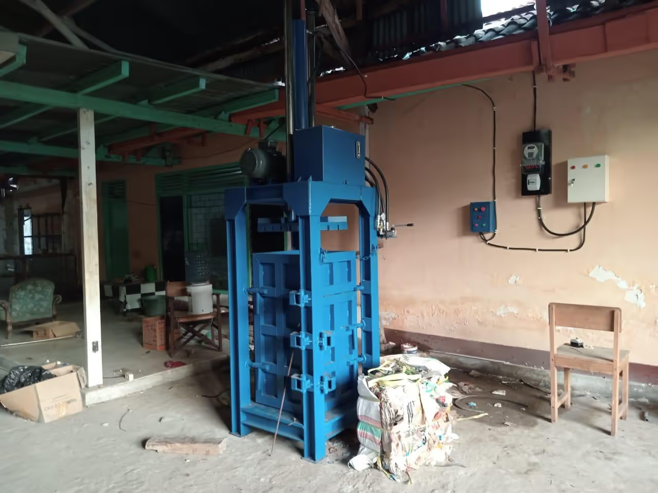
Wedoo automatic baler machine

OTHER MACHINE
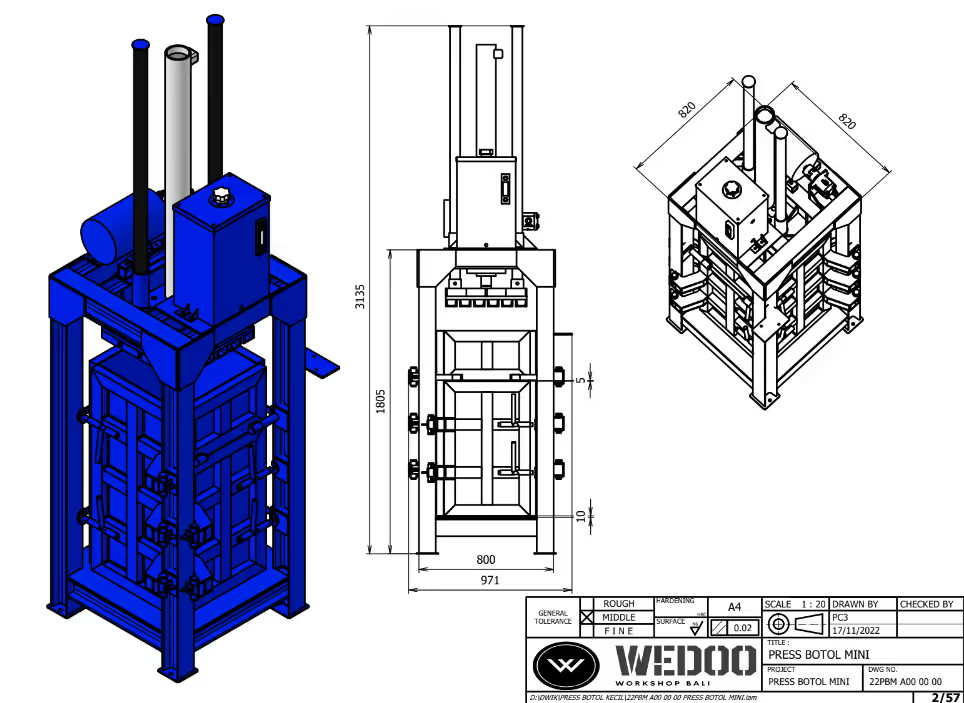
Specification:
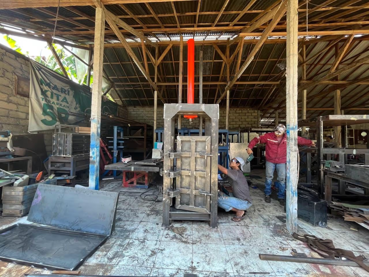
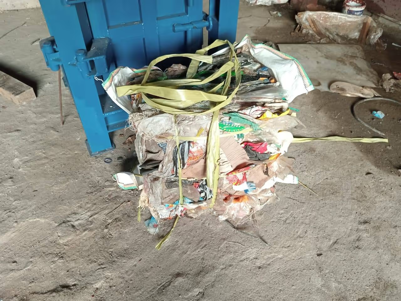
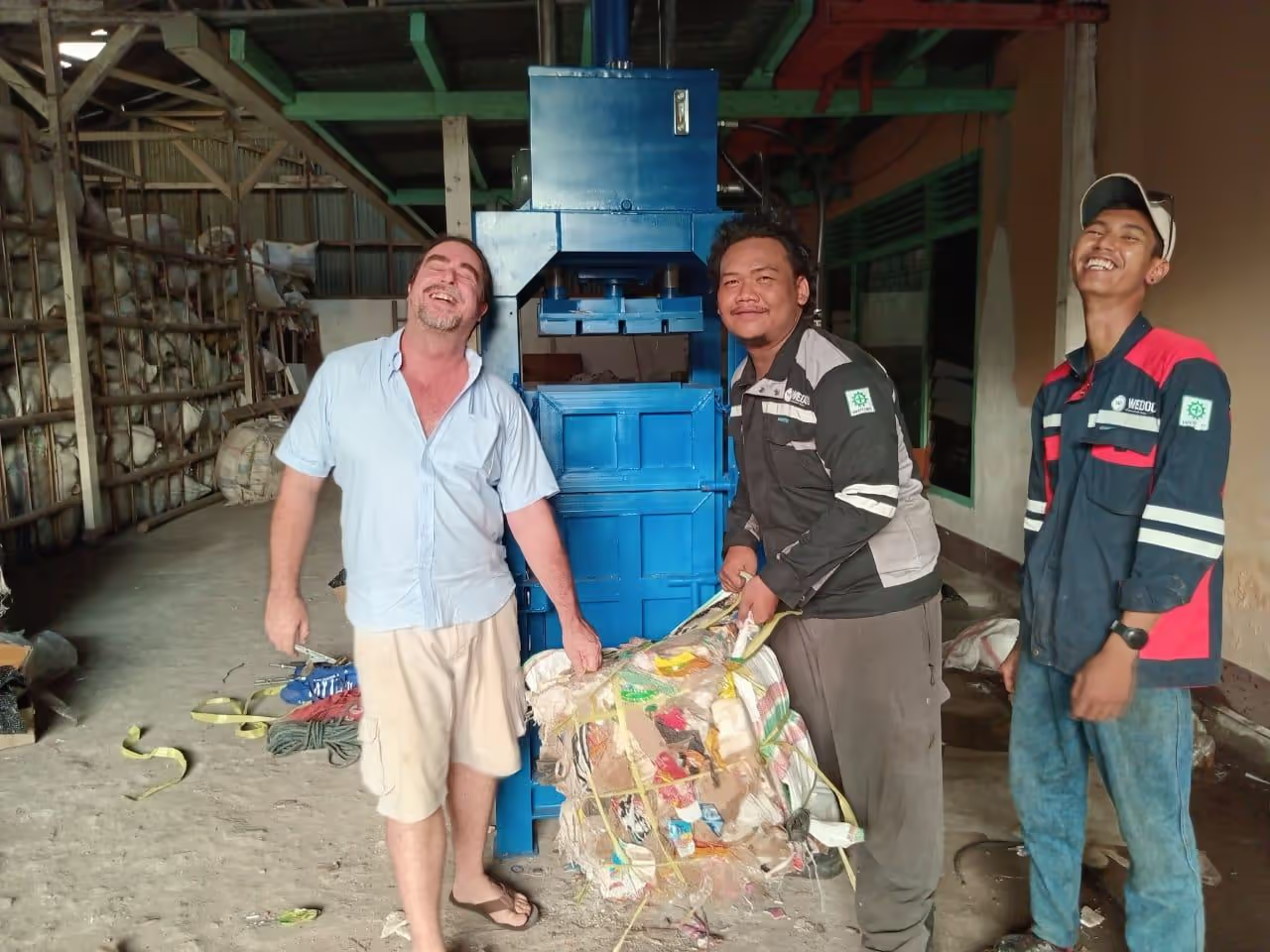
The automatic baler compresses waste with hydraulic pressure and binds it with twine or wire. This process minimizes manual handling and enhances safety. It efficiently reduces storage space requirements and waste collection frequency, optimizing waste management.
Additional images and videos are available here.
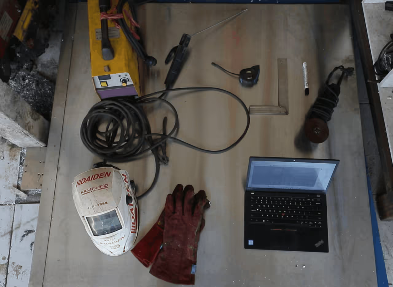
These are the skills and machinery needed for machine building:
Machinery and Tools:
Personal Protective Equipment (PPE):
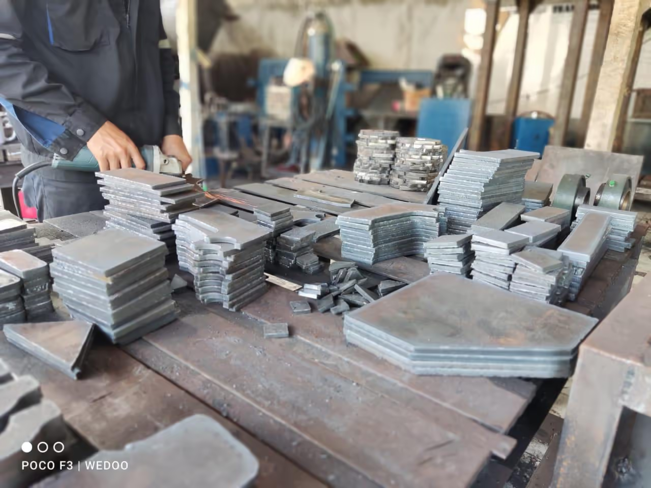
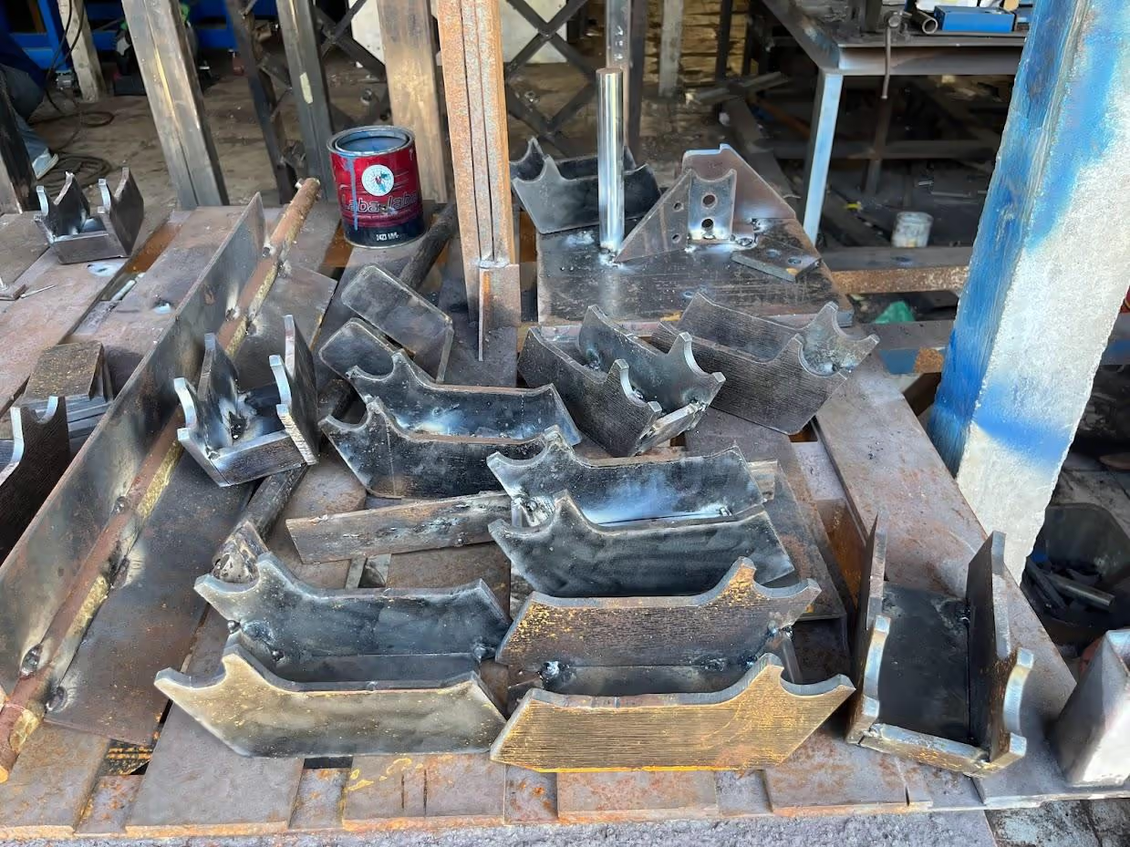
Download the plasma cutter files and follow the instructions to cut the machine parts according to the metal plate thickness. Alternatively, you may bring these files to a local machine shop for cutting.
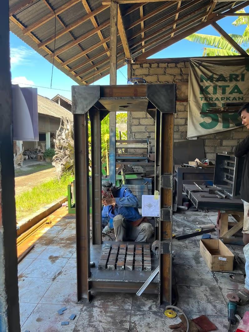
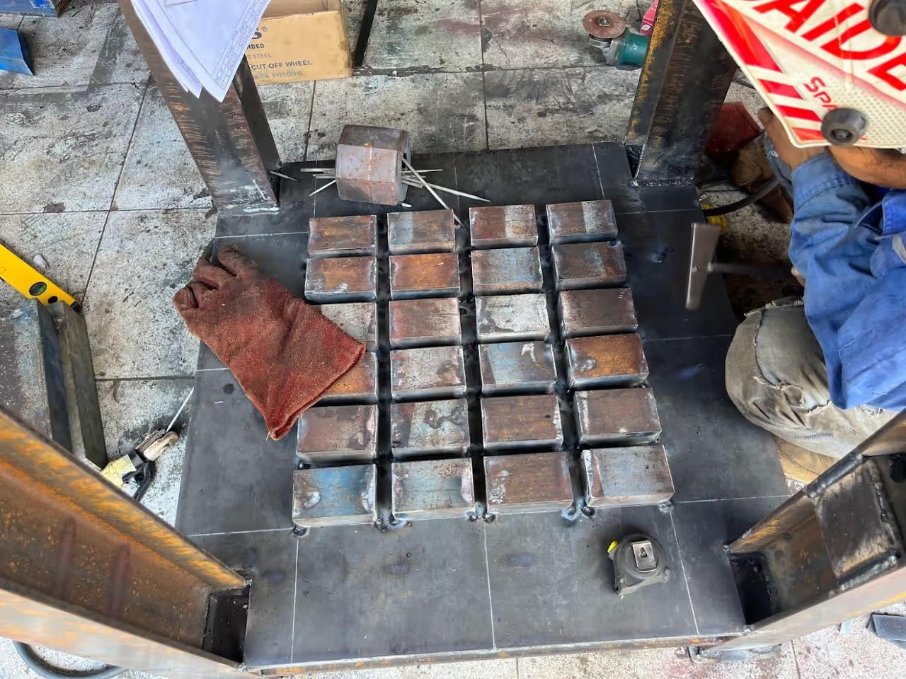
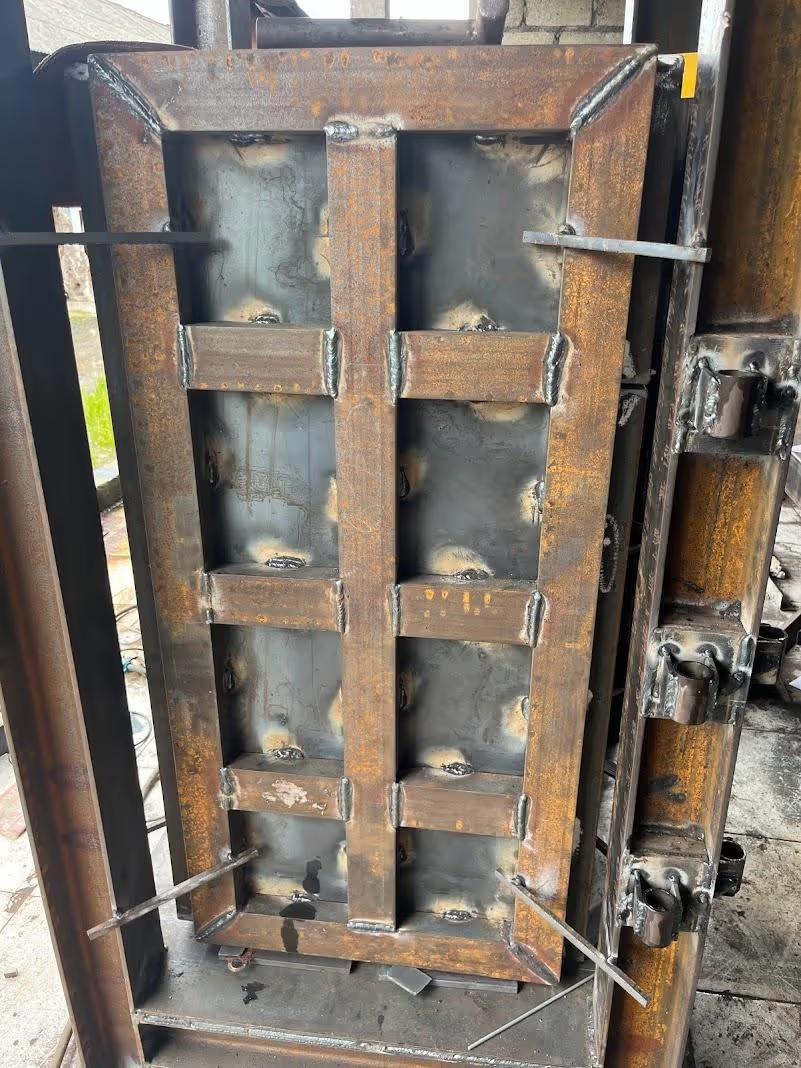
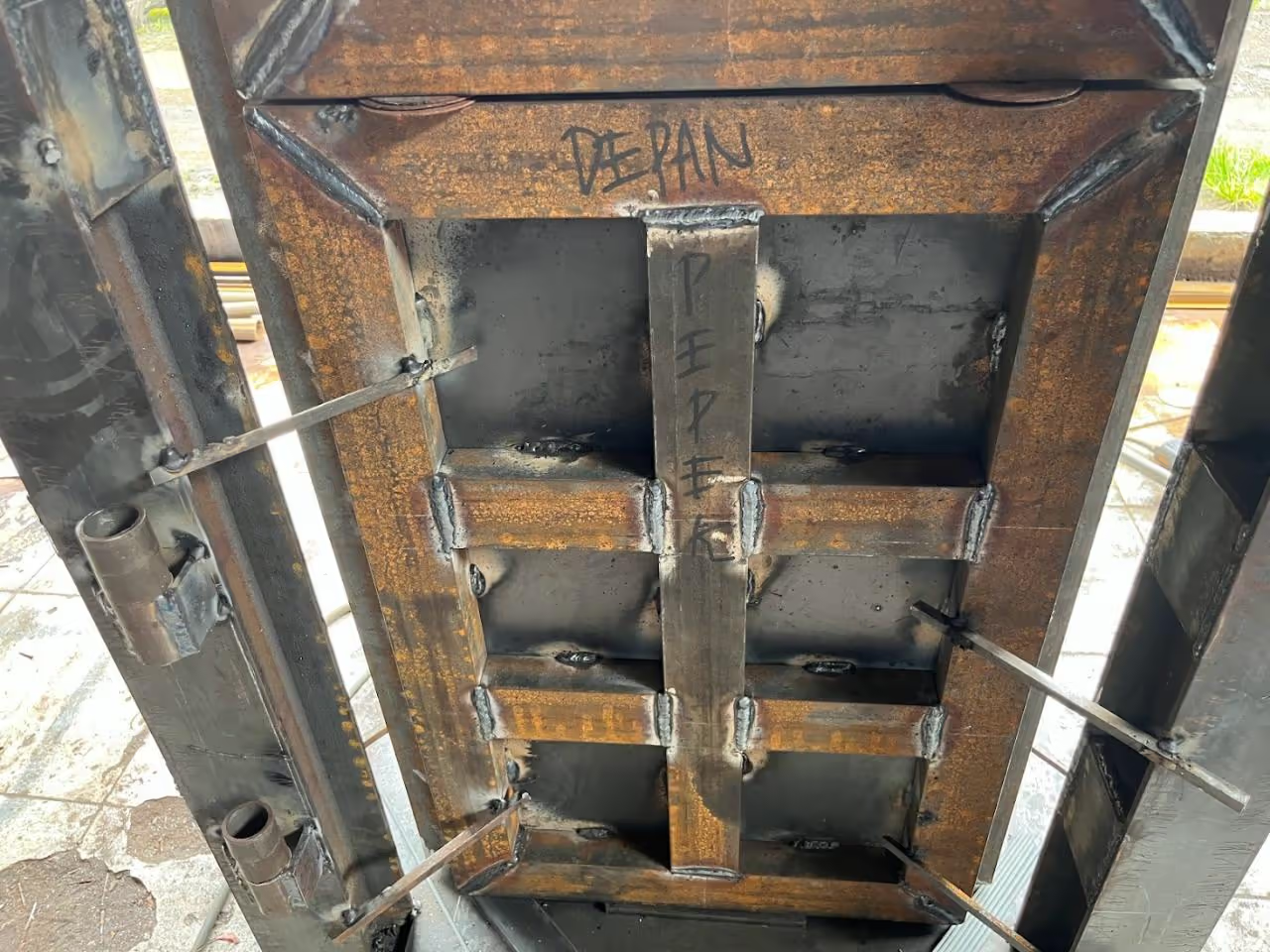
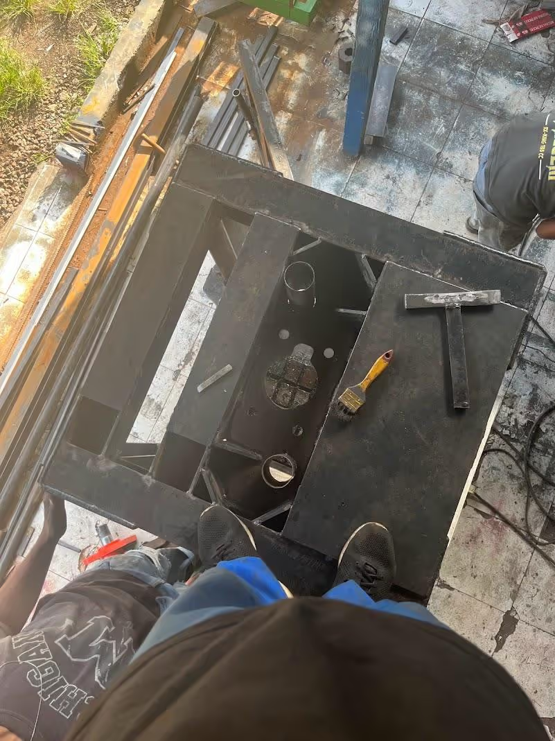
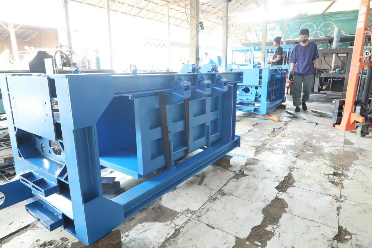
Construct the main frame as per the design specifications. For the baler's base, fabricate a platform grid to accommodate the twine or string. Ensure precise welding to form the grid and accurately position it at the frame's bottom.
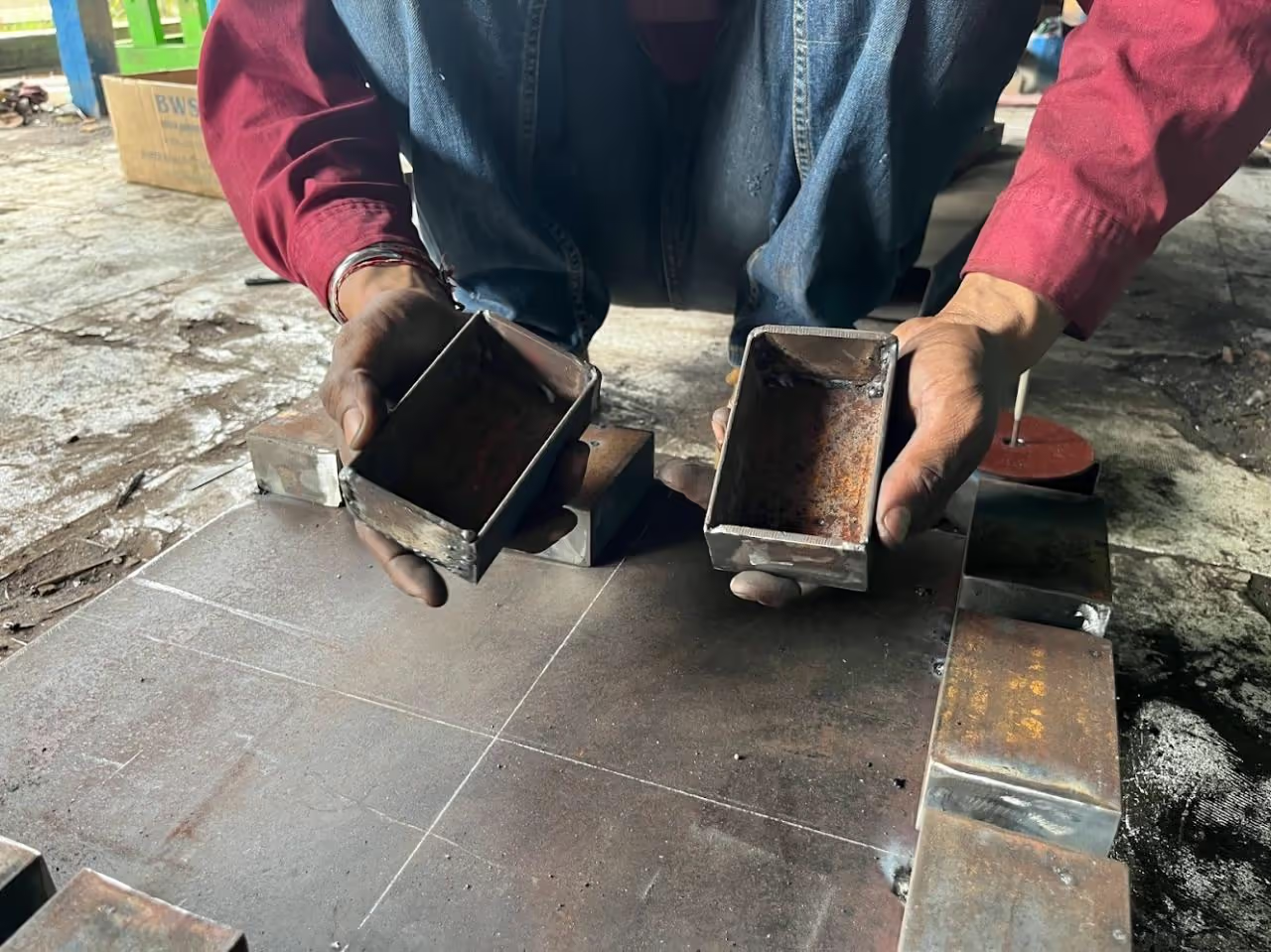
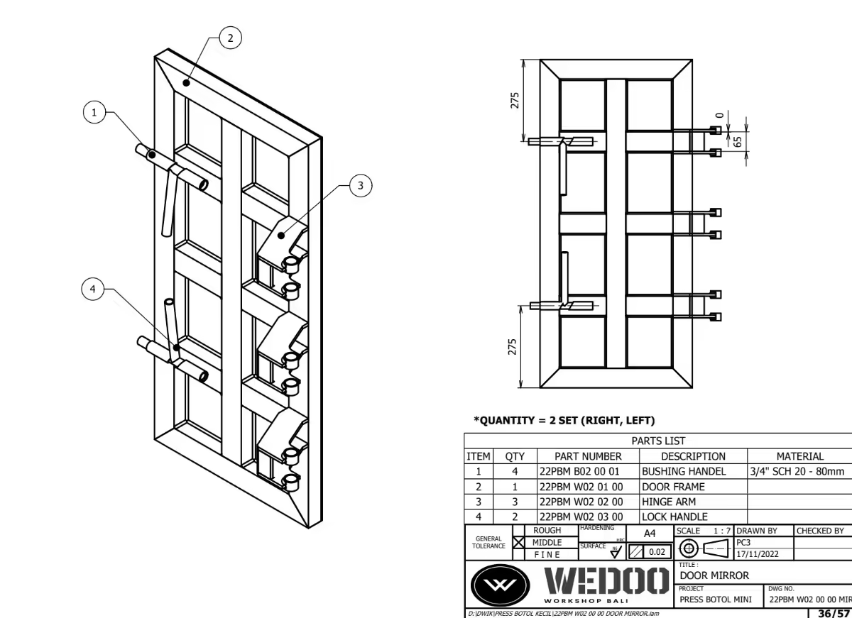
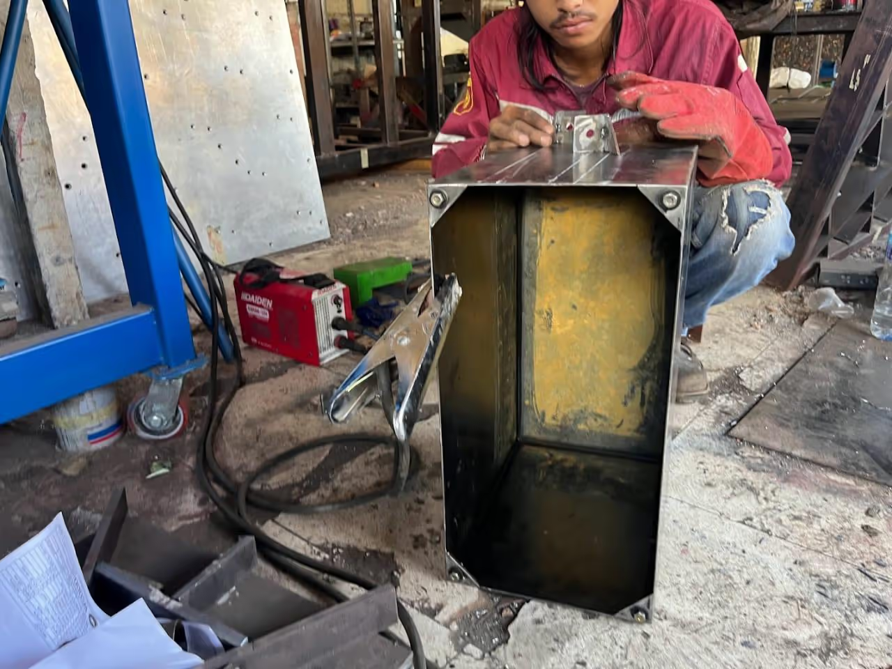
A hinge comprises two parts: one fixed to the door and the other to the frame. Cut all parts using a plasma cutter and weld them together.
After crafting hinges and locks, attach the hinges to the main frame first (see step 7).
Each side of the door has unique hinge and lock placements; follow the design carefully.
The front door is designed to fold down, allowing easier access for loading materials.
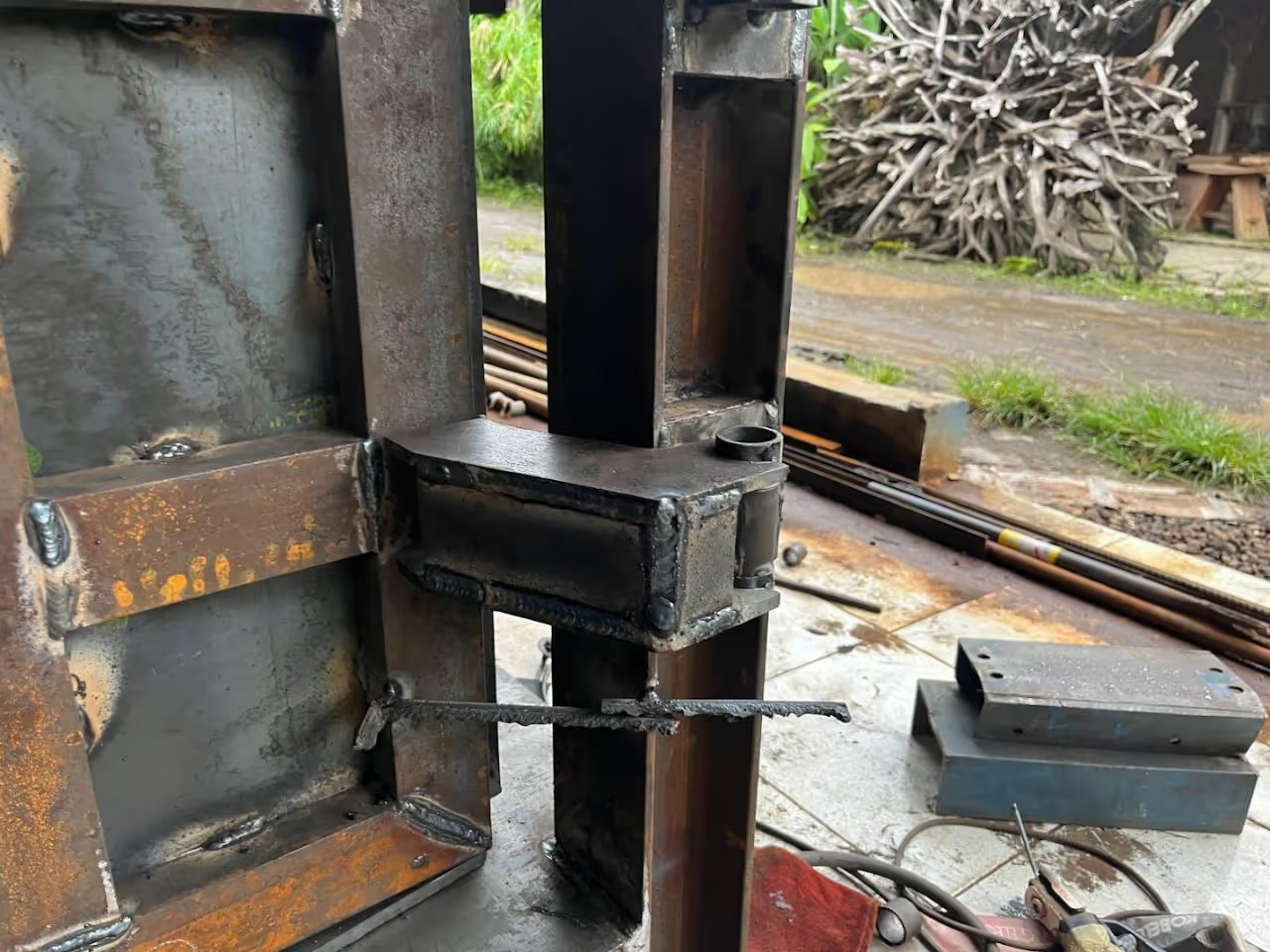
If you are uncertain about precise welding, do not attach the hinge to the door until ensuring all components are aligned (refer to step 7).
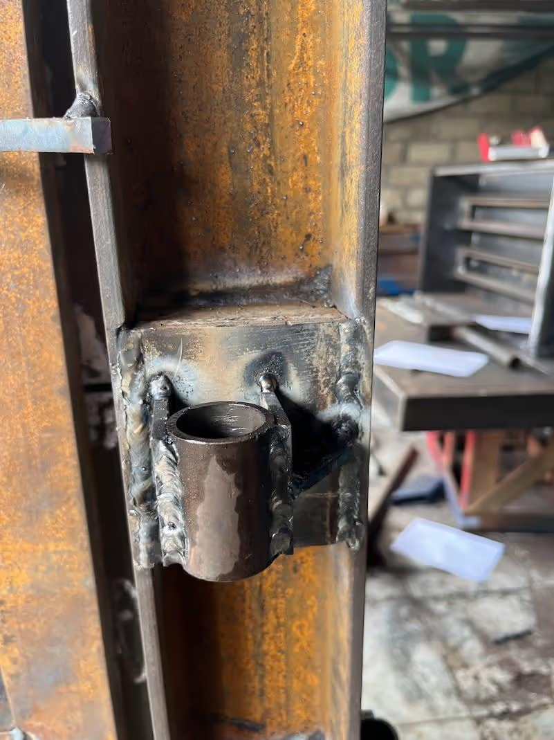
To ensure proper alignment of your doors, weld the hinge only after positioning the door correctly. Use the hinge on the frame as a guide for smooth movement. You may weld a temporary support, as shown in the picture, to aid alignment. Once the hinges are aligned with the frame, remove the temporary support.
Remove any excess material from the welding process to ensure smooth operation of all hinges and locks. Properly aligned, all four doors should open and close with ease.
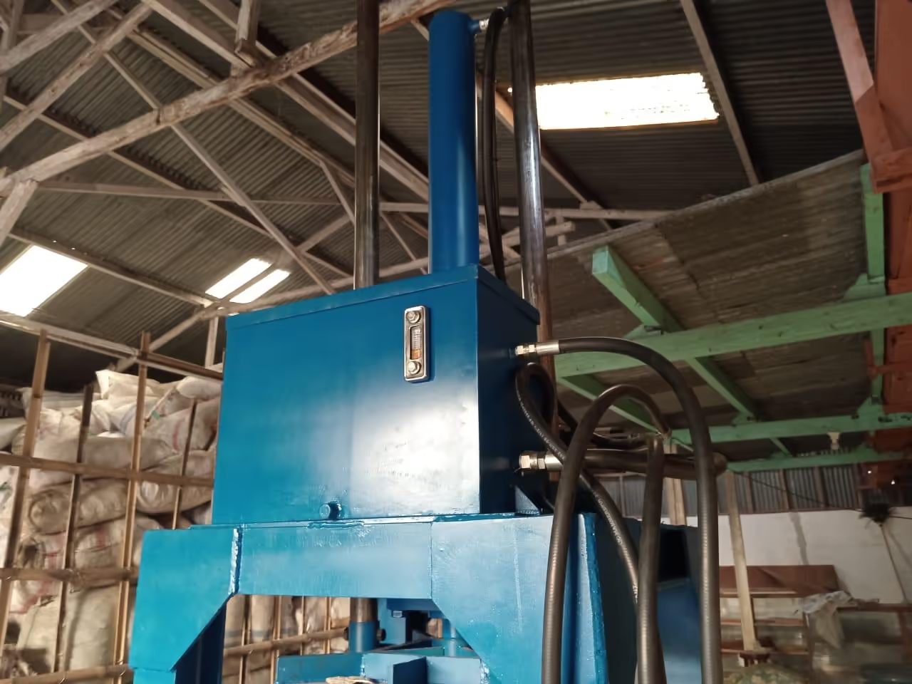
Ensure all seams are leak-free. Attach to the upper section of the baler according to the 3D drawing.
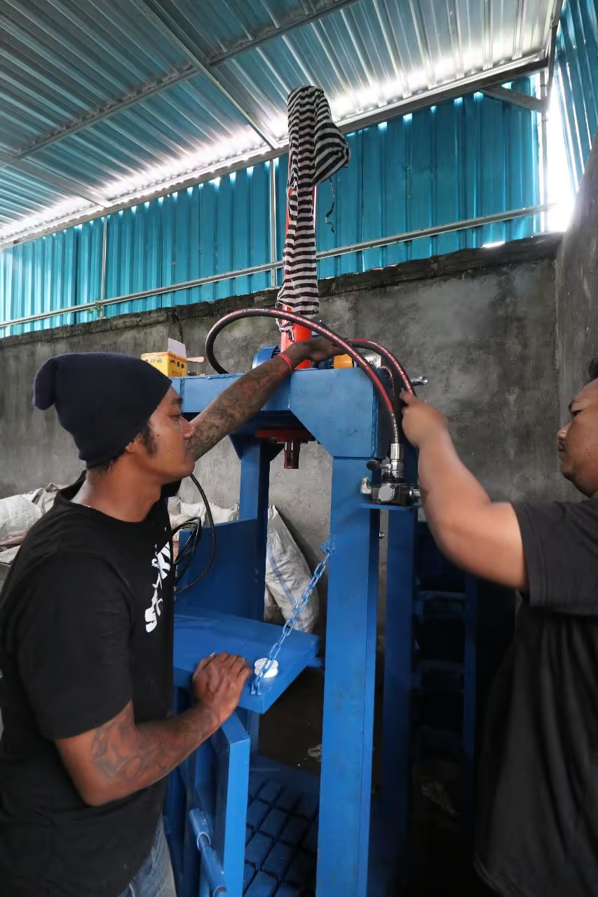
A team is required due to the heavy hydraulics. Two strong individuals should be positioned above as receivers, with two others lifting and one securing it from below.
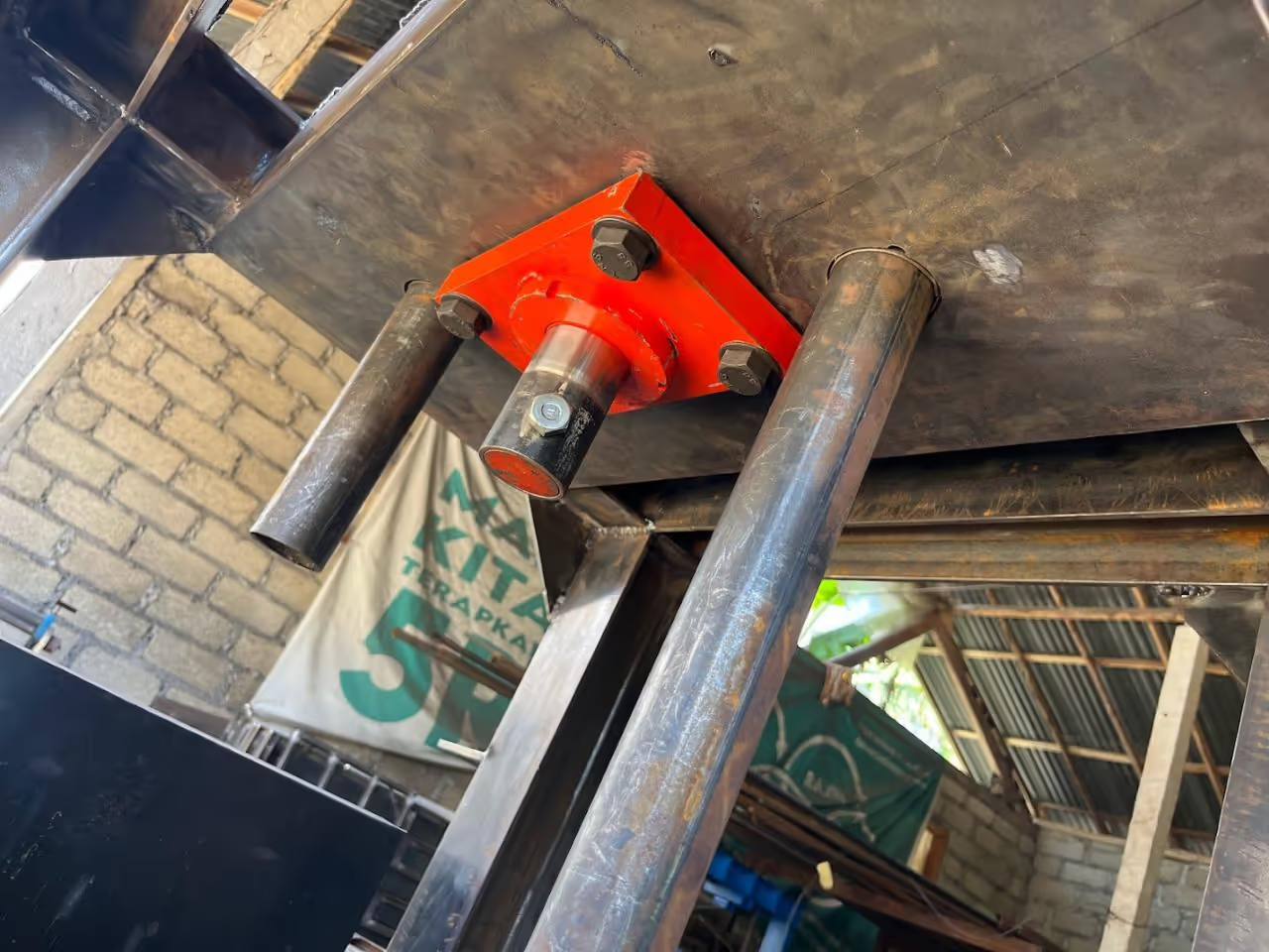
Elevate the hydraulic and secure it in place.
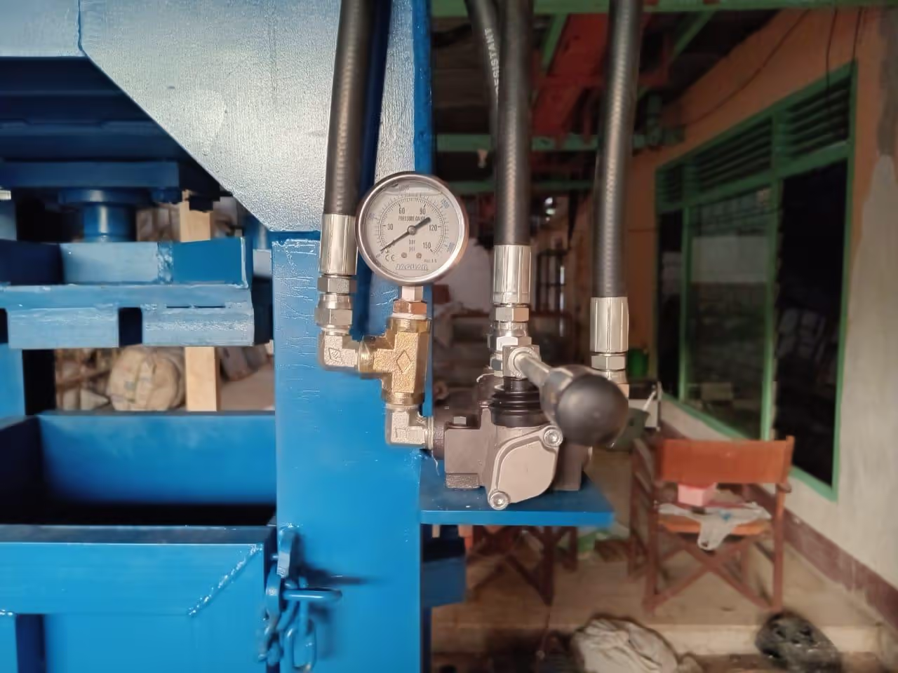
Attach the remaining components:
Test your machine to ensure proper functionality.
Once you confirm all parts are operational, disassemble the components before painting the frame.
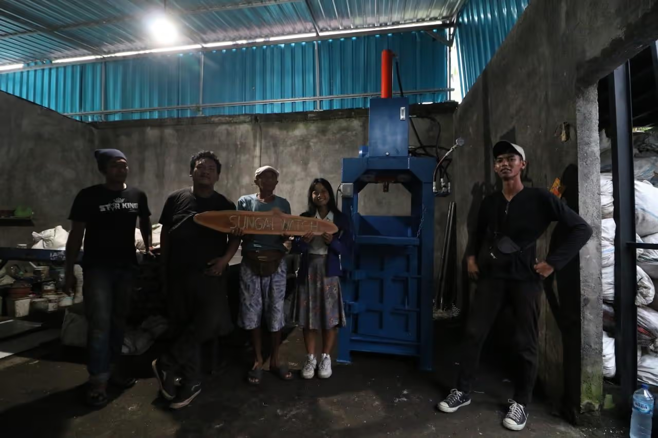
We recommend placing your machine on a level surface, and securing it to the floor for greater stability.
Open source technology plays a vital role in developing solutions that can be shared and enhanced by a global community of makers, engineers, and designers. By making our design open source, we aim to foster collaboration, innovation, and creativity.
We welcome your thoughts, feedback, and suggestions on our open source automatic baler machine. Whether you have engineering experience or are an enthusiastic maker, your ideas are valuable to us. Please visit our profile for contact information.
Thank you,
Wedoo Team