Build your own filament cooling system
EXTRUSION
UNTAGGED
MELTING
PRODUCT
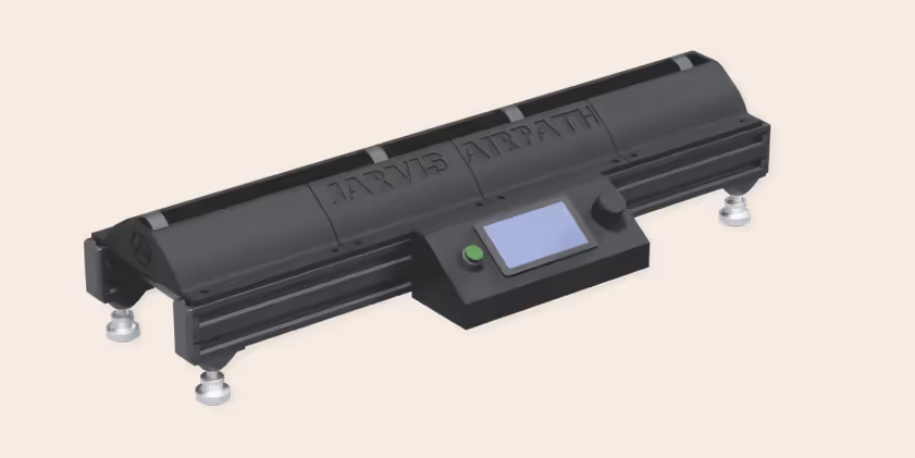
Assemble your JARVIS Airpath cooling system in six simple steps.
For assistance, access our video tutorial: Watch Video
For further information, visit our website:
Visit Qitech
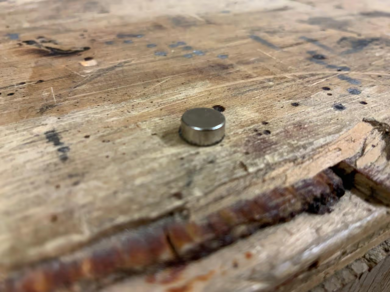
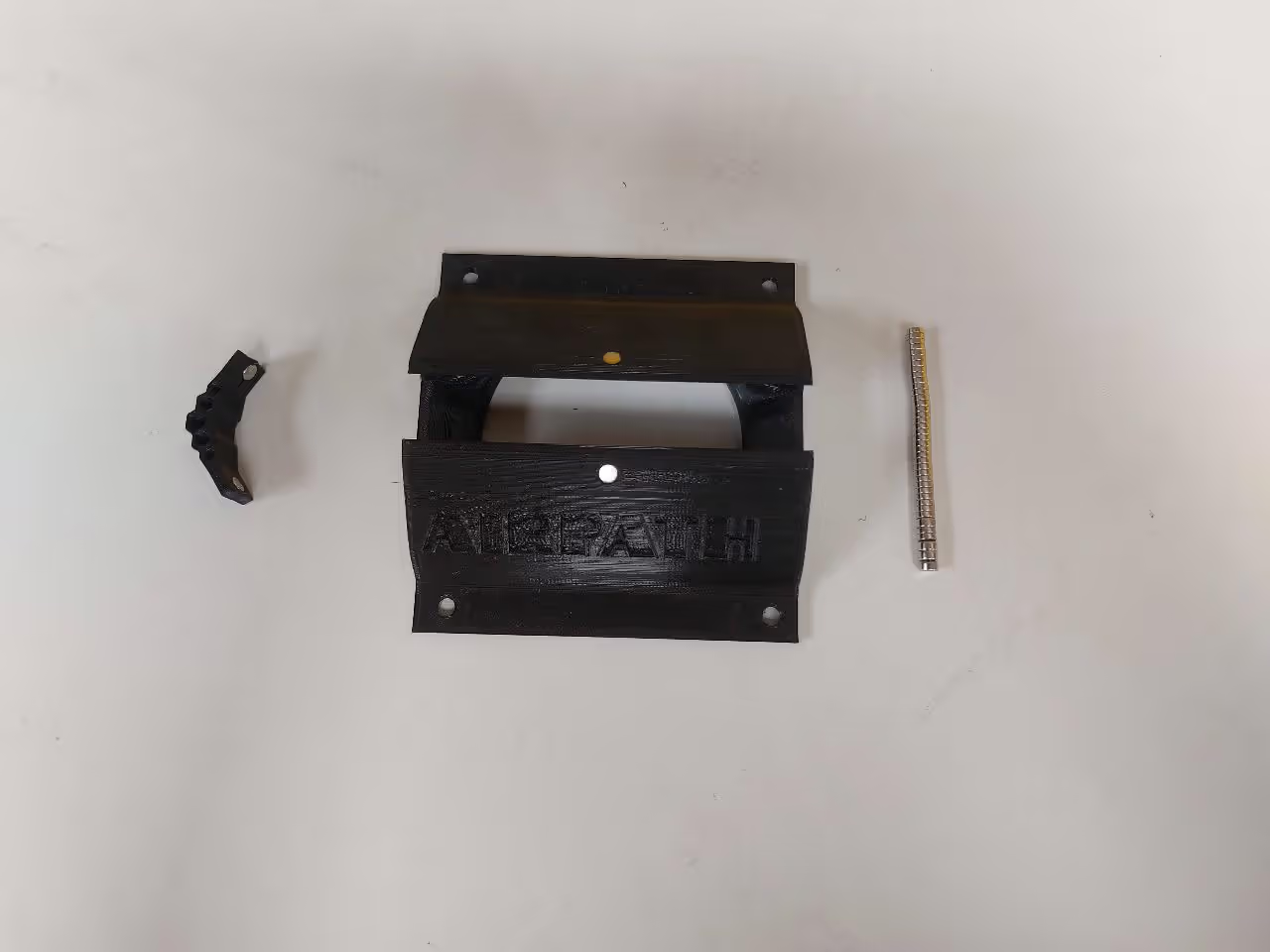
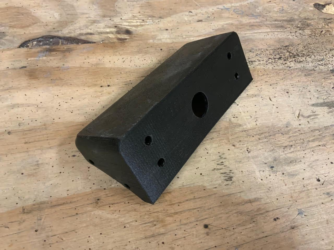
First, prepare the four gondolas by inserting the included magnets into the upper holes. Ensure all magnets in the gondolas have the same polarity for proper interaction with the magnetic clips.
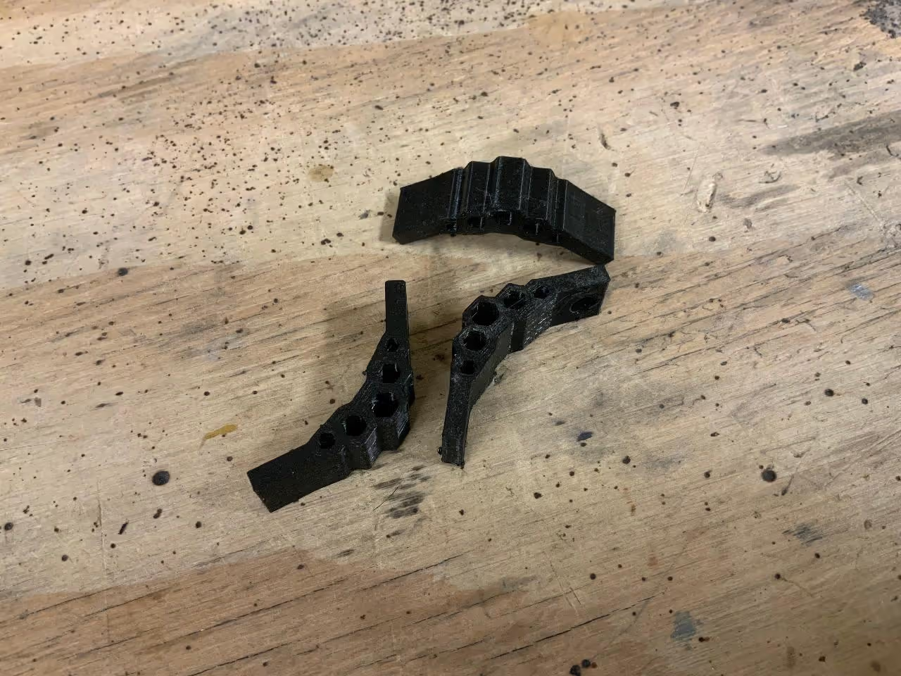
The clips contain two interior holes for magnets. Insert the magnets with the correct orientation to ensure they attract the gondolas.
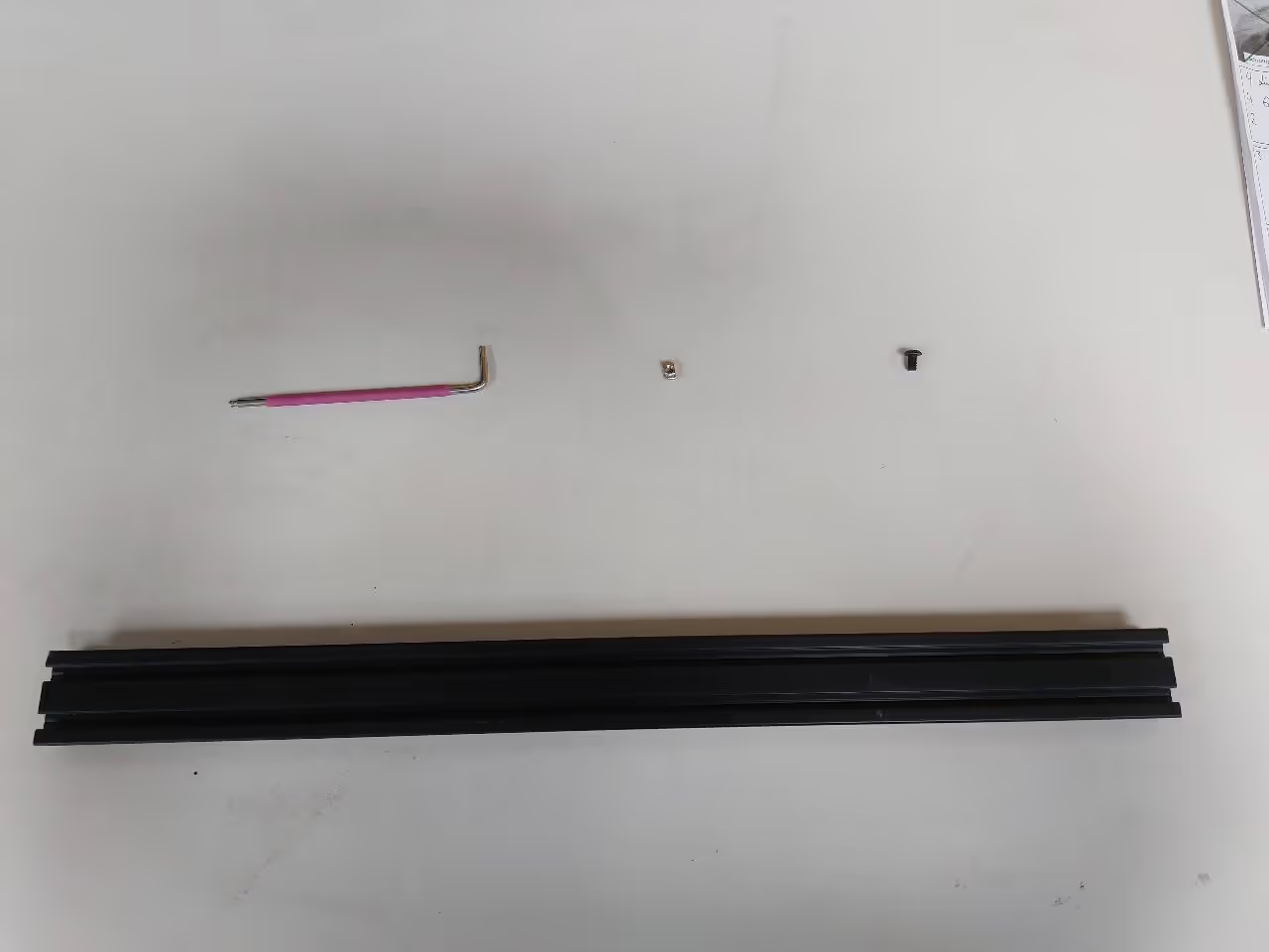
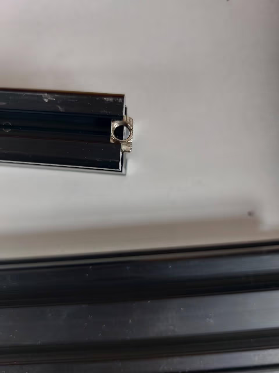
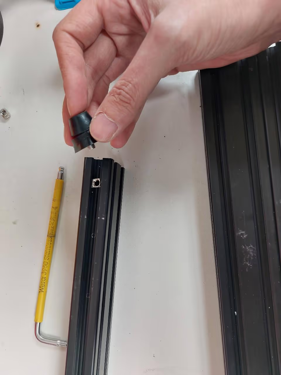
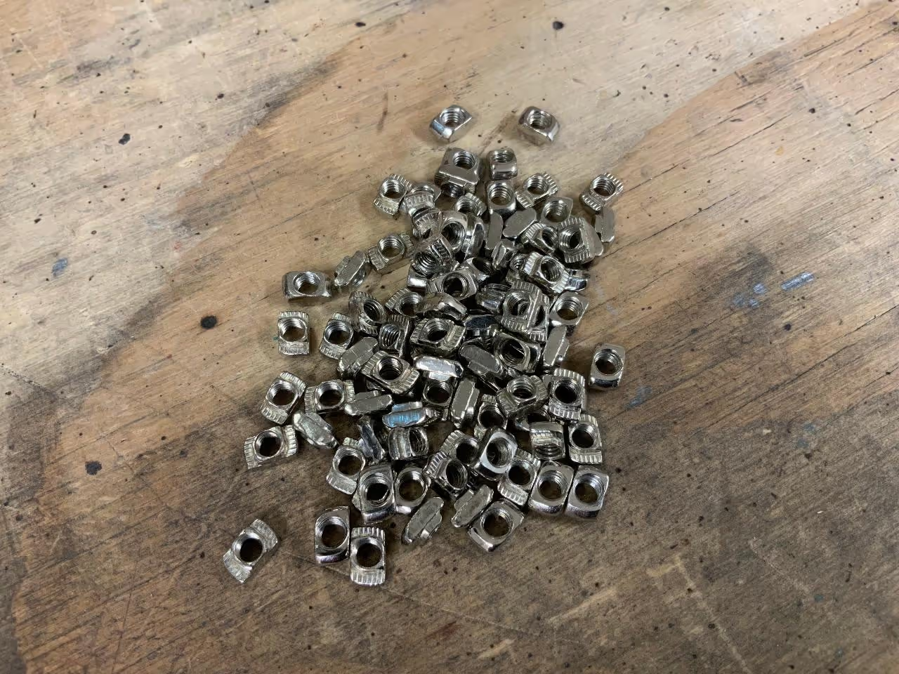
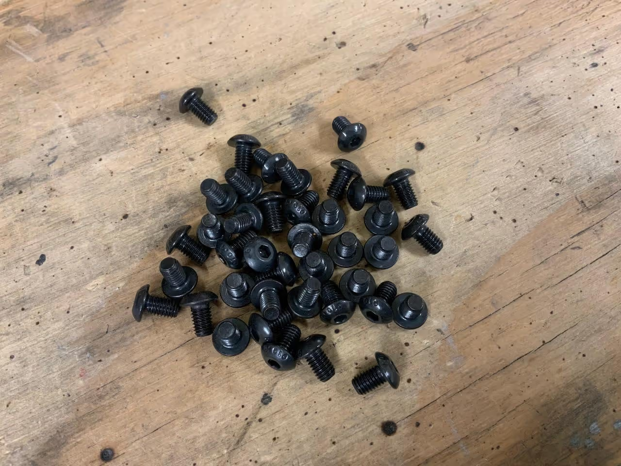
Attach the four gondolas to the aluminum profiles using 16 M5 x 8 screws and 16 T-nuts. You will need a 3 mm (0.12 in) Allen key.
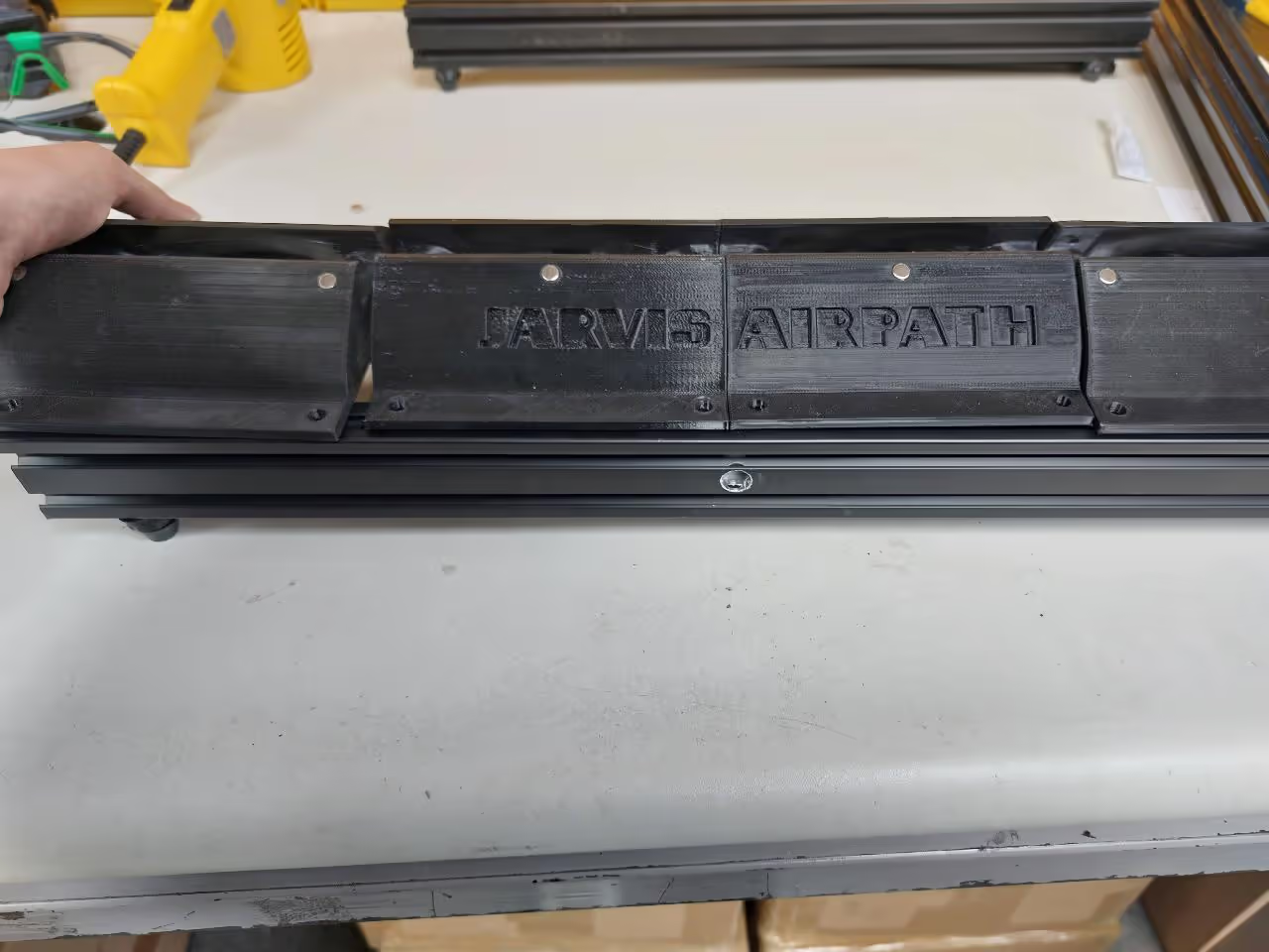
Ensure the front side is visible and accessible; the aluminum profiles have a designated hole for this. Slide the T-nuts into the profiles, with the rounded side facing down. Secure the gondolas to the profiles with the screws, following the specified order. The outer gondolas should have their logos facing outwards, and the inner ones should show labeling. Make sure gondolas do not extend past the aluminum profiles—these should extend about 2 mm (0.08 in) outward.
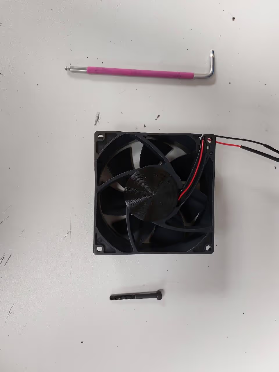
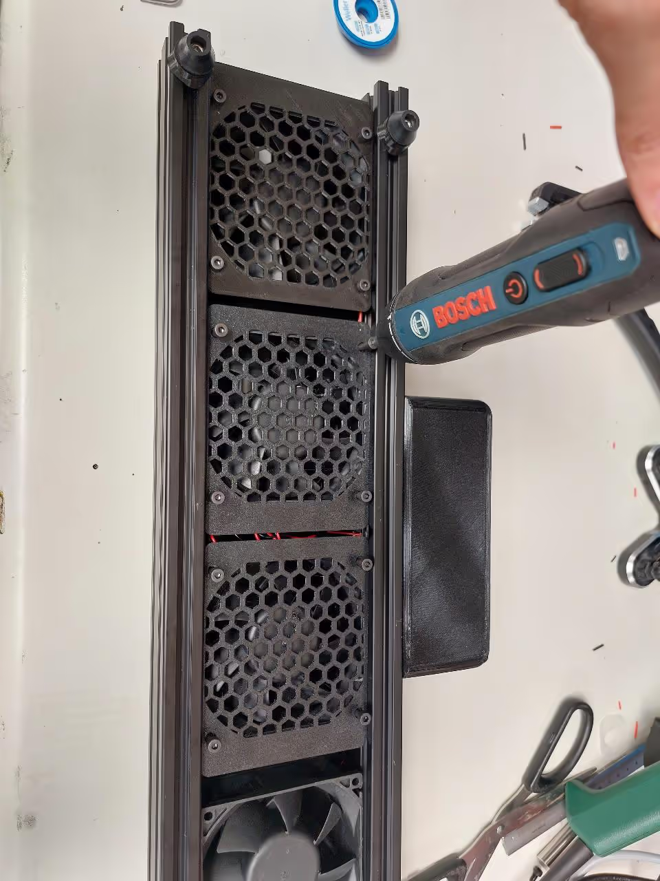
Insert the fans into the JARVIS Airpath, ensuring the cone tips face inward and the display cables are pulled through the aluminum profile (aluminium profile), ensuring cables do not impede fan rotation. Secure the grilles and fans onto the gondola.
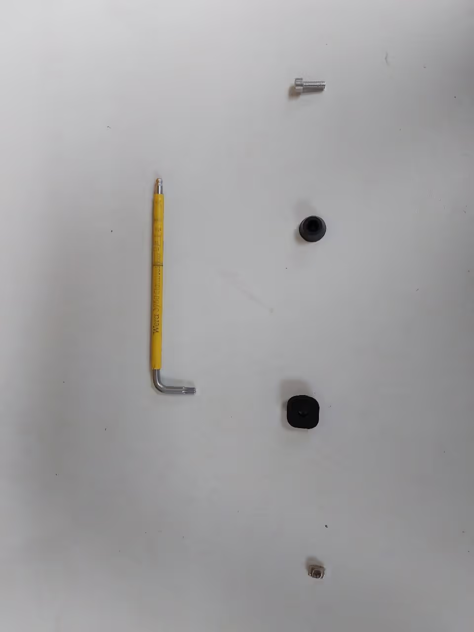
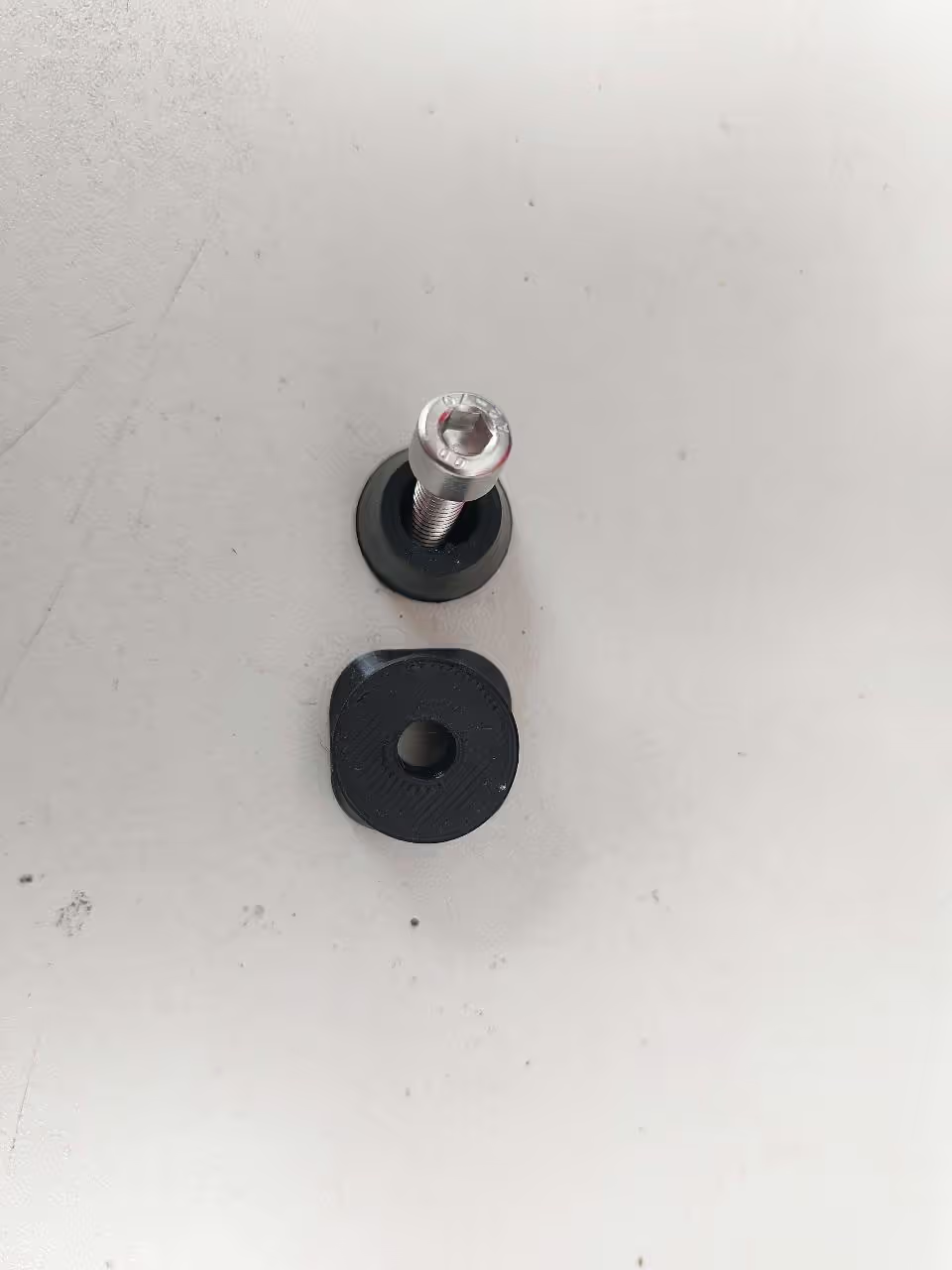
To securely screw in the feet, you will need 4 T-nuts, 4 hard plastic washers, 4 rubber feet, 4 screws (M5 x 14 or 0.2 x 0.55 inches), and a 4 mm (0.16 inch) Allen key.
Place the JARVIS Airpath on the rubber feet. Position the hard plastic washers between the rubber feet and the aluminum profile. Screw two support feet into the aluminum profile.
Attach the control box using four T-nuts and four M5 x 8 (5/16 in x 5/16 in) screws. Insert the T-nuts into the aluminum profile and secure the control box to the front. Ensure power cables are routed through the hole into the box.
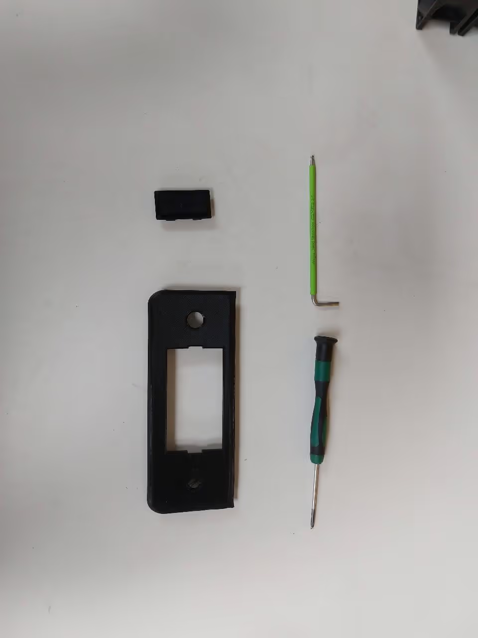
You need the control cover, display box, DC jack, four set screws, an Allen wrench (2.5 mm/0.1 in), and a small screwdriver (0.35 mm/2.5 mm or 0.014 in/0.098 in).
Open the display box and remove the green start button.
Attach the display to the control cover, ensuring the black border faces downward. Insert the fan control through the smaller hole and the green start button through the larger hole, securing it with a thin metal ring and nut.
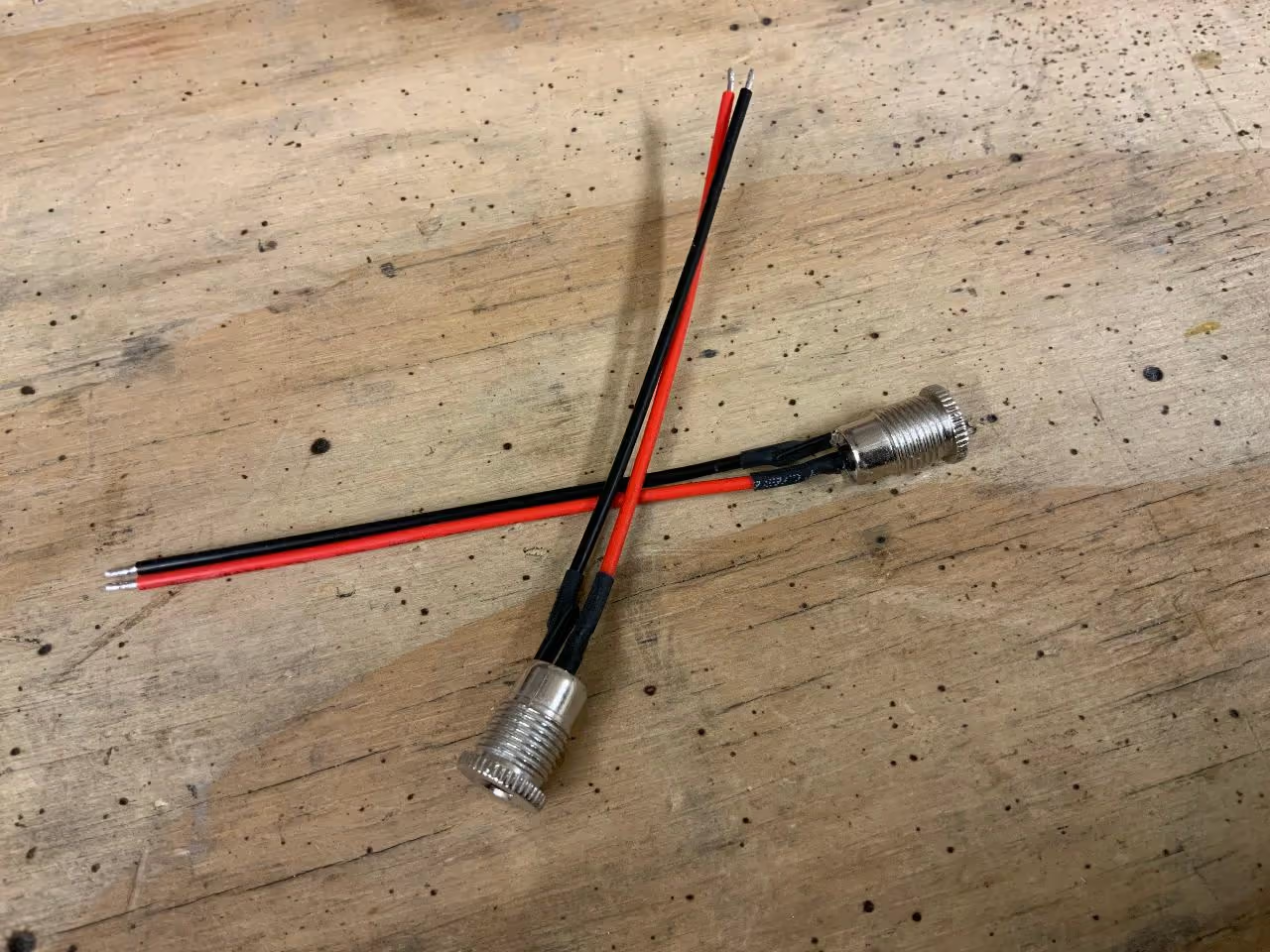
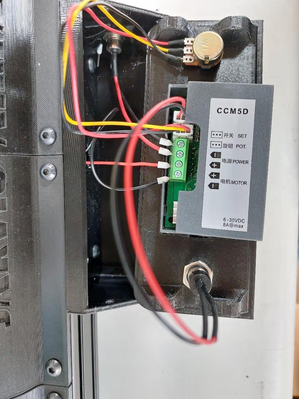
Install the DC jack through the side hole of the control box and thread the cables into the box.
Screw the black cables into the "-" terminal and the red cables into the "+" terminal before closing the box.
Use set screws to secure the control box to the display cover.