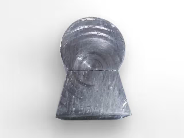
Broom hanger mould
PRODUCT
MOULD
INJECTION
A wall-mounted clamp for brooms and mops can be made by following these steps to create its mold for an injection machine.
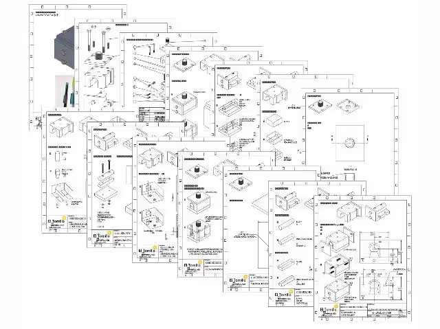
Ensure all materials are prepared and carefully review the attached drawings and steps to fully understand the process, enhancing efficiency and accuracy.
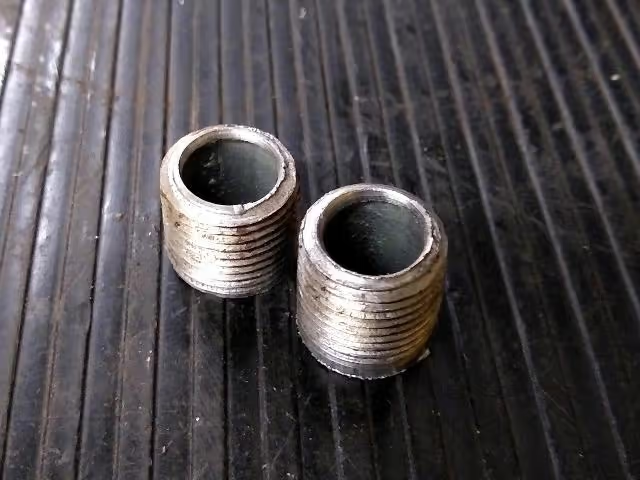
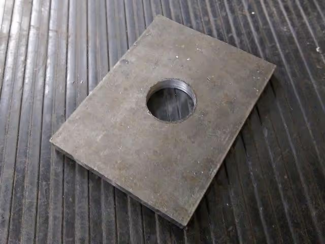
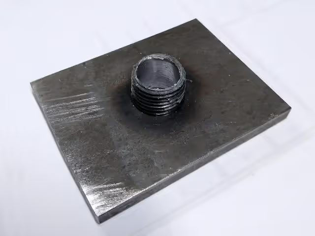
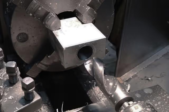
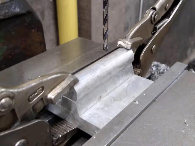
Begin by cutting the steel pipe nipple (no. 7) in half to create the mold nozzle. Drill a hole in the center of the metal sheet (no. 8) to securely fit one half of the pipe nipple. Weld parts no. 7 and no. 8 together, and then chamfer the welded edge on the lathe.
(Drawings page 3-5)
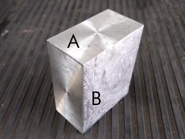
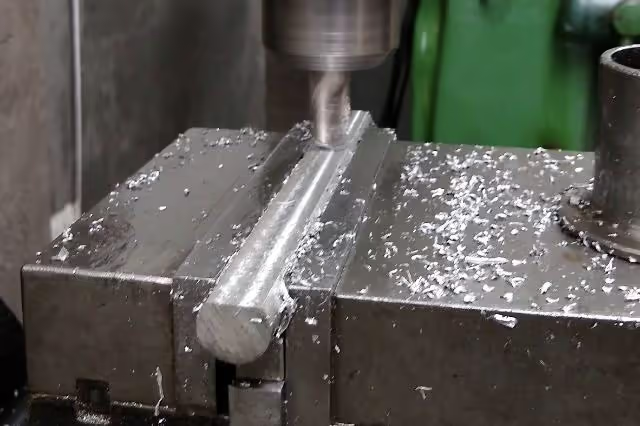
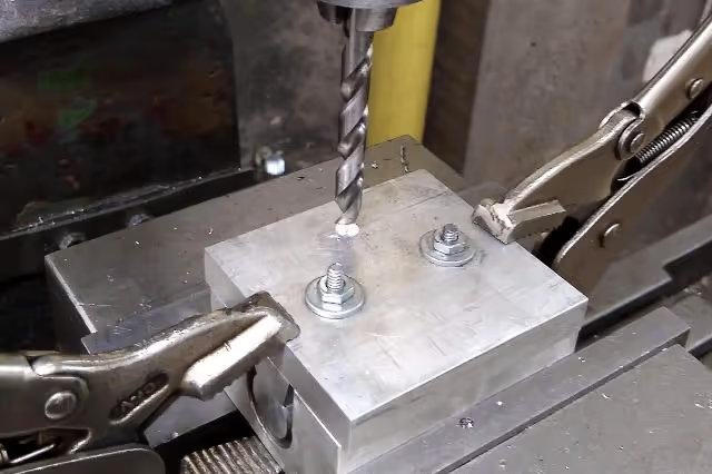
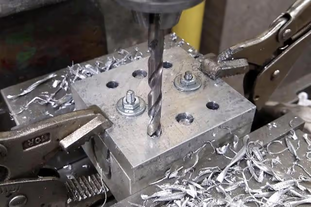
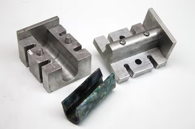
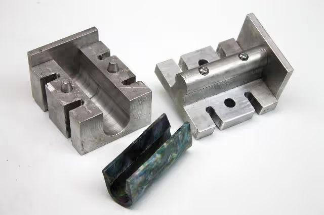
Create the female mold by taking aluminum block no. 1 and drilling a hole that is 1 inch (2.54 cm) deep in the center of face A. Begin with smaller drill bits, gradually increasing to 1 inch (2.54 cm). Next, mill face B to create a channel 1 inch (2.54 cm) wide. Utilize a round point bit for a smoother finish.
(Refer to drawings on page 6)
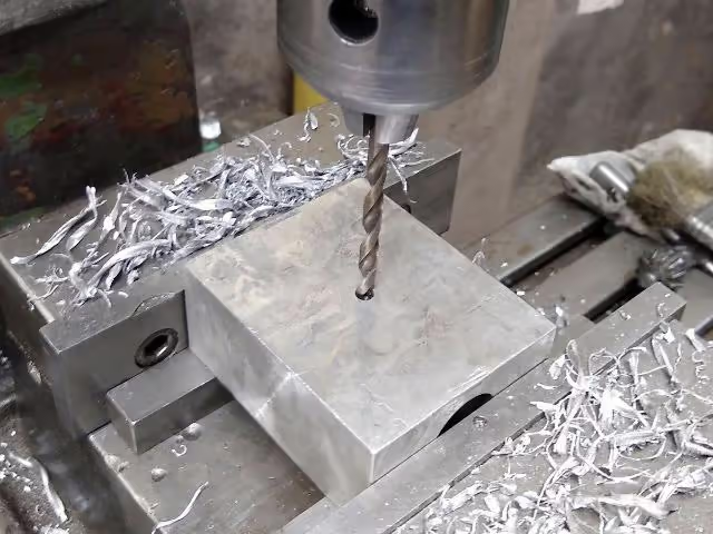
Drill a 5 mm (0.2 in) hole through the center of the female mold.
(Drawings page 6)
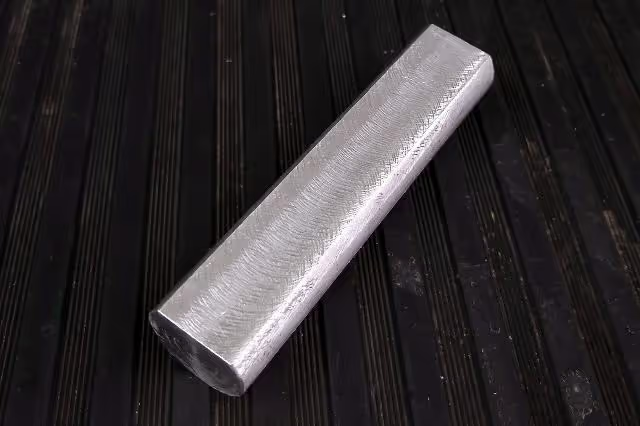
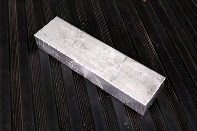
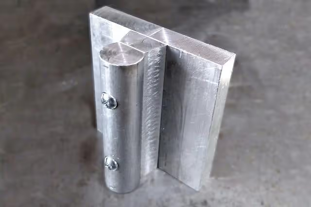
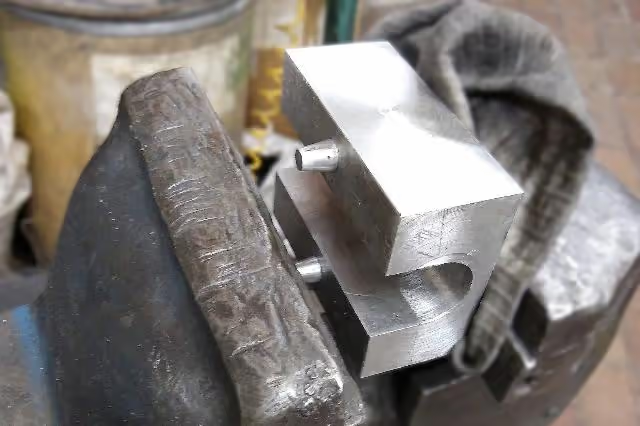
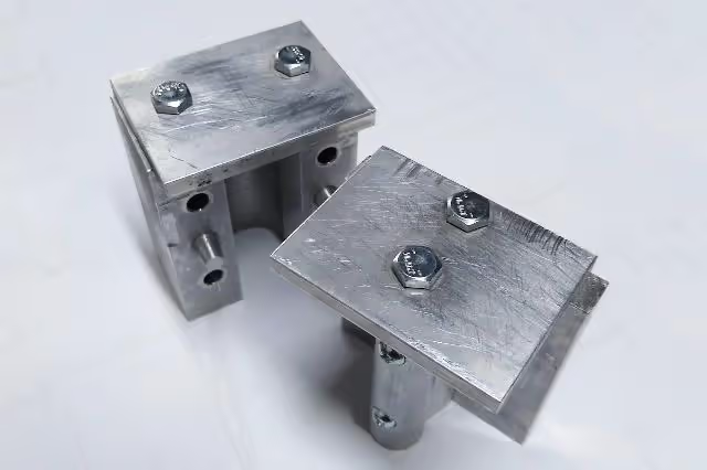
The male mold consists of three parts. Prepare aluminum parts 2, 3, and 5. Begin with the aluminum rod (part 5). Mill one side of the rod to a height of 3.17 mm (1/8 inch) and a width of 14.19 mm (9/16 inch).
(Refer to drawings on page 7)
Take part no. 3 and mill one face at a 15° angle. Then mill the opposite face to a 15° angle until the narrow face measures 14.19 mm (0.56 inches) and the wider face measures 21 mm (0.83 inches), matching the face of part 5. Refer to drawings on page 7.
To assemble the male mold, align the centers of the previous parts with part no. 2. Secure with clamps and drill two holes, 3/16 inch (4.76 mm) deep. On part no. 5, drill flat countersinks for screw no. 9 heads. Use button head screws, washers, and nuts (no. 9-11) to fasten the three parts.
(Drawings pages 8-9)
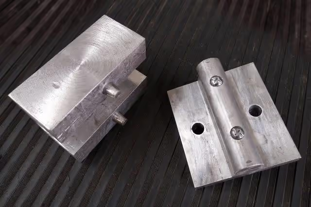
Align the female and male parts of the mold and secure them with a small press or locking pliers. Mark the hole positions from the drawings onto the face of part 2 and drill two holes with a 9.5mm (3/8 inch) diameter. Drill through part 2 and 1cm (0.39 inch) deep into part 1.
(Refer to drawings on page 10)
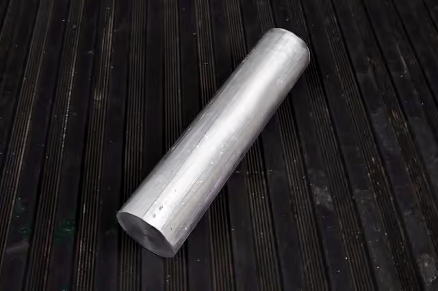
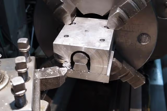
Turn the round metal bar (no. 6) to create the conical guides. Saw a channel on one side to allow air flow during insertion. Using a vice or hammer, insert the conical guides into part no. 1.
(Refer to drawings on page 11)
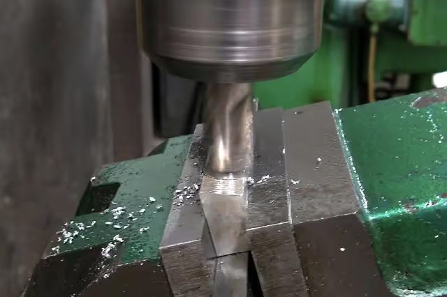
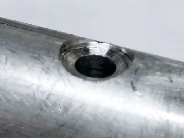
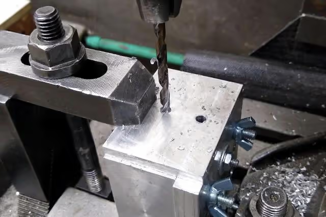
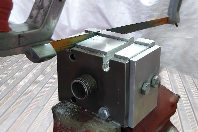
Fix the nozzle by securing the female and male parts with a small press or locking pliers, then drill four 9/32" (7 mm) holes at the corners of both parts. Close the mold and adjust the ends for an even surface between the male and female parts.
(Drawings page 12)
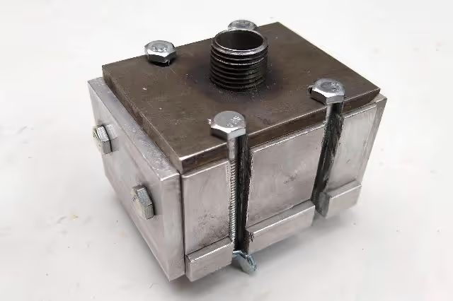
Secure each cap (no. 4) and drill four holes with a 5mm (3/16 inch) diameter through the cap, penetrating 25mm (1 inch) into both female and male mold parts. Tap each hole in the female and male sections with a ¼ inch thread. Enlarge the holes in the caps to ¼ inch and secure them with bolts (no. 12).
(Refer to drawings on page 13)
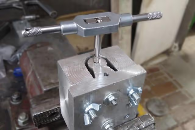
Final Step: Use a hand saw to cut two slots per side for easier bolt insertion and removal. Secure the mold with four bolts and butterfly nuts (size 13-14).
Refer to Drawings on page 14.
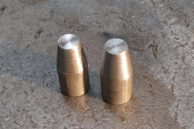
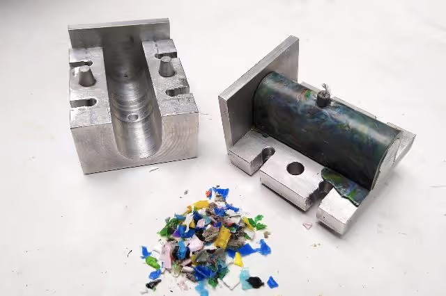
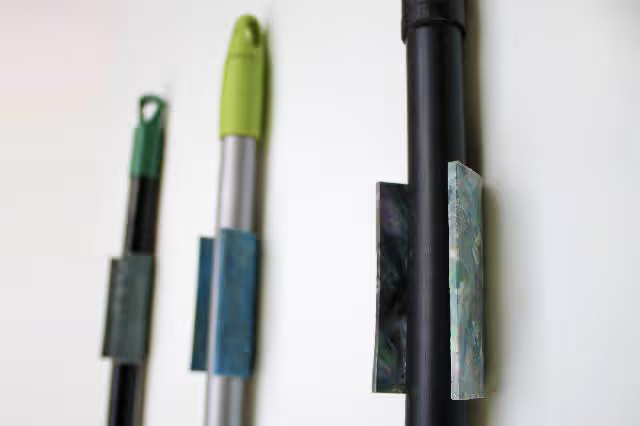
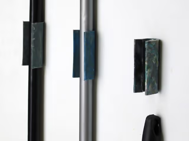
The broom hanger mold is complete and ready for injection. Flexible plastics such as HDPE and PP are recommended as they are less prone to cracking.
To open the mold, use a flat screwdriver to gently separate the parts. To remove the plastic product, use a flat screwdriver or putty knife to detach it from the male mold. It is advisable to perform this while the plastic is still warm, but ensure the mold is returned to its original shape afterward.
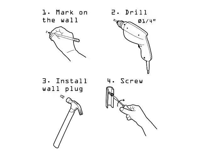
To install the broom hanger, drill a hole in the wall, insert a wall plug, and secure it with a screw.
Technical drawings (pages 3–14) are critical for dimensional accuracy. Prioritize precision tools and alignment during assembly.